


Page 12
GV100W BOILER
INSTALLATION & OPERATING INSTRUCTIONS
INSTALL MANUAL
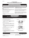
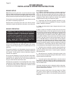
SHUT-OFF VALVE
5 FT. ABOVE FLOOR
WHERE REQUIRED BY
LOCAL CODES
GAS SUPPLY
PIPING
SEDIMENT TRAP
OR
DRIP LEG
(TO EXTEND TO FLOOR)
FLOOR LEVEL
GROUND JOINT
UNION
GAS INLET
TO
BOILER
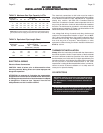
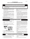
10
8
6
4
2
0
0 5 10 15 20 25
FLOW - GPM
HEAD - FEET OF WATER
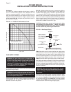
TACO 007 CIRCULATOR
PERFORMANCE CURVE
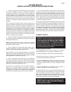
Circulators
The TACO 007 circulator supplied with the boiler is sized for
use in a closed heating system with a 30 psi,
207 kPa
maximum operating pressure. If the 007 circulator does not
have the required capacity for the system in which it is to be
installed, an extra zone circulator or a higher capacity circulator
will be needed. FIG. NO. 11 depicts the performance curve for
the TACO 007 circulator.
FIG. NO. 11 TACO 007 Performance Curve
GAS SUPPLY PIPING
WARNING: All gas piping must be installed by a
qualified technician in accordance with the provisions
set forth in the latest edition of ANSI Z223.1/NFPA 54
and all applicable local building codes and
regulations. A licensed propane installer must make
all LP gas connections. Improper gas connections
could result in a fire or an explosion!
The GV100W hot water boiler comes from the factory ready to
be piped to the gas supply.
WARNING: Check the boiler rating plate and make sure
that the boiler is for the type of gas that will be used. If
it isn’t Do not connect the boiler to the gas supply or a
fire or an explosion may occur!
If for any reason the boiler is not for the type of gas available at
the installation site, call the nearest Smith Cast Iron Boiler
distributor to resolve the problem.
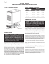
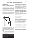
FIG. NO. 12 depicts the proper way to connect the boiler to
the gas supply piping. The manual shut-off valve MUST be
installed in the supply piping. It should be approximately 5 ft,
1.5 m
, above the floor. Provide a sediment trap/ drip leg at the
bottom of the vertical section of the gas supply pipe. A ground
joint union should be installed between the boiler gas controls
and the supply piping. Each of these items are needed to
ensure long life and ease of servicing. Always use a pipe
sealant that is suitable for use with LP gas.
CAUTION: Always use a wrench on the gas valve body
when making gas connections to it. Never over-tighten
the piping entering the gas valve body. Failure to comply
with this caution may result in gas valve failure!
FIG. NO. 12 Gas Supply Piping
Table 3 should be used to ensure that the gas supply piping
is sized properly. If more than one appliance is supplied by the
same supply pipe, the piping must be sized based on the
maximum possible demand. Do not neglect the pressure drop
due to pipe fittings. Table 4 should be used in conjunction with
Table 3 to ensure that the gas supply piping is sized properly.
Safe lighting and other performance criteria were met with the
gas manifold and control assembly provided on the boiler when
the boiler underwent tests specified in ANSI Z21.13/CAN 4.9.
All gas connections must be leak tested before putting the
boiler into operation.
WARNING: Never use an open flame to test for gas
leaks. Always use an approved leak detection method.
Failure to comply with this warning could result in an
explosion!
Whenever the gas supply piping is pressure tested the boiler
gas controls must be protected. If the test pressure is equal
to, or less than 1/2 psig,
3.5 kPa
, isolate the boiler by closing
it’s manual shut off valve, see FIG. NO. 8. If the test pressure
is greater than 1/2 psig
3.5 kPa
, disconnect the boiler and it’s
individual shut-off valve from the gas supply piping.