


Page 13
GV100W BOILER
INSTALLATION & OPERATING INSTRUCTIONS
Nominal Iron Pipe length
Pipe Size 10' 20' 30' 40' 50' 60' 80' 100' 150'
3⁄4" 278 190 152 130 115 105 90 79 64
1" 520 350 285 245 215 195 170 150 120
11⁄4" 1050 730 590 500 440 400 350 305 250
11⁄2" 1600 1100 890 760 670 610 530 460 380
Note: Maximum pipe capacity in ft
3
/hr based on 0.60 specific gravity
gas at pressures of 0.5 psig or less and a 0.3 " WC pressure drop.
TABLE 3 Maximum Gas Pipe Capacity in ft
3
/hr
TABLE 4 Equivalent Pipe Length Chart
Equivalent length of pipe fittings in feet
Nominal Iron Type of Pipe Fitting
Pipe Size 90° Elbow Tee Gate Valve Gas Cocks
(branch flow) (full port)
3⁄4" 2.06 4.12 0.48 1.25
1" 2.62 5.24 0.61 1.60
11⁄4" 3.45 6.90 0.81 2.15
11⁄2" 4.02 8.04 0.94 2.50
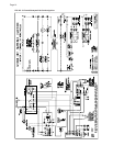
ELECTRICAL WIRING
Electrical Power Connections
CAUTION: Label all wires prior to disconnection when
servicing controls. Wiring errors can cause improper and
dangerous operation!
ATTENTION: Au moment de l’entretien des commandes,
étiquetez tous les fils avant de les débrancher. Des erreurs
de câblage peuvent entraîner un fonctionnement in-adéquat
et dangereux. S’assurer que l’appareil fonc-tionne
adéquatement une fois l’entretirn terminé.
Page 13
GV100W BOILER
INSTALLATION & OPERATING INSTRUCTIONS
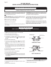
The electrical connections to this boiler must be made in
accordance with all applicable local codes and the latest edition
of the National Electrical Code, ANSI/NFPA-70. Installation
should also conform with CSA C22.1 Canadian Electrical
Code Part I if installed in Canada. Install a separate 120 volt 15
amp circuit for the boiler. A shut-off switch should be located at
the boiler. The boilermust be grounded in accordance with the
authority having jurisdiction, or if none, the latest edition of the
National Electrical Code, ANSI/NFPA-70.
Line voltage field wiring of controls and other devices must
conform to the temperature limitation of type T wire at 95°F,
35°C
, above room temperature. Use copper conductors with a
minimum size of #14 awg. Low voltage wiring must not be less
than #18 awg with a neoprene, thermoplastic or other
equivalent insulation having a minimum insulation thickness of
0.012 in,
0.3 mm
.
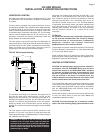
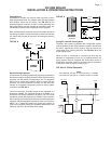
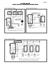
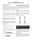
THERMOSTAT INSTALLATION
Always follow the instructions included with the thermostat to
be used to control the boiler. Proper location of the thermostat
will ensure efficient trouble-free operation of the boiler. Mount
the thermostat to an inside wall at a height approximately five
feet above the floor. Avoid placing the thermostat in areas that
will not provide an accurate measurement of the room
temperature. Locating the thermostat behind a door, in an alcove,
close to a source of thermal radiation or in a drafty area will
cause poor or sporadic heating.
CO DETECTORS
WARNING: Installers must follow local regulations with
respect to the installation of CO detectors and follow
the manufacturer’s stated maintenance schedule for
this boiler!
ATTENTION: Observer les règlements règional à l'egard
des détecteurs de monoxyde de carbone et observer
entretien de manufacturier pour cette chaudière!