


Page 11
GV100W BOILER
INSTALLATION & OPERATING INSTRUCTIONS
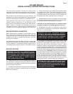
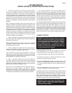
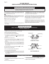
Pumped Blend
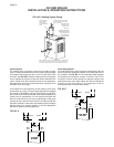
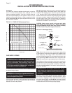
An additional circulator can also be used to provide a return
water temperature blend. This method works well with systems
with multiple zones with circulators, see FIG. NO. 8. The
dedicated bypass circulator provides a strong blending flow
without diminishing the flow available to any heating zone. Any
residentially sized circulator is adequate for this purpose.
Each of these bypass solutions also has the added benefit of
increasing circulation in the boiler which will maximize tankless
coil output and increase the accuracy of temperature sensing
controls.
FIG. NO. 8
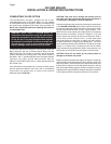
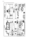
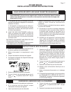
Reverse Acting Aquastats
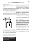
An alternative for existing systems experiencing condensation
that does not require re-piping the boiler utilizes a reverse acting
aquastat, one that makes on temperature rise. This approach
works best in single zone systems. Wired in series with the
circulator, this control holds the circulator off until the boiler
reaches an acceptable temperature and then starts system
circulation, see FIG. NO. 9.
The most commonly available reverse acting aquastat is a
Honeywell L4006B. The aquastat should be mounted in an
immersion well directly installed in the boiler. The use of heat
conductive grease (Honeywell part # 972545) in the immersion
well is strongly recommended for fast and accurate temperature
response. Set this adjustable aquastat to make at no less than
130° F,
54° C
. While this method can cause the circulator to
cycle more frequently, setting the aquastat’s differential to the
maximum (25-30°F) will minimize short cycling.
SUPPLY
RETURN
100%
120° F
200%
140° F
200%
160° F
100%
160° F
100%
160° F
PUMPED
BYPASS
reverse
aquastat
N.O.
T
T
t'stat
GV
115 volts
24 volts
circulator
operating
aquastat
N.C.
REVERSE
AQUASTAT
SET AT 120° F
FIG NO. 9
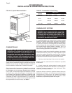
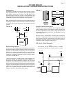
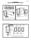
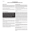
Piping For Use With Cooling Units
The boiler, when used in connection with a refrigeration system
must be installed so the chilled medium is piped in parallel with
the boiler. Appropriate valves must be used to prevent the
chilled water from entering the boiler. See FIG. NO. 10 for the
proper piping layout.
When a boiler is connected to a heating coil that may be
exposed to refrigerated air from an air handling device, the
piping system must be equipped with flow-control valves or
some other automatic means of preventing gravity circulation
of the boiler water during the cooling cycle.
FIG. NO. 10 Chiller Schematic
NOTE
FOR HEATING: VALVES "H" OPEN, VALVES "C" CLOSED.
FOR COOLING: VALVES "H" CLOSED, VALVES "C" OPEN.
EXP. TANK
VENT
ROOM
UNIT
DRAIN
CHILLER
H
C
PUMP
RELIEF
VALVE
FILL
VALVE
DRAIN
H
BOILER
C