


19A SERIES BOILER
INSTALLATION INSTRUCTIONS
PAGE 8
15. CONTROL LOCATIONS
NOTE
Jacket front panel should be in place before controls on
front of front section are installed.
Refer to FIGURE 11 showing locations recommended for
steam and water boiler limit and operating controls. Note the
requirement for an operating temperature control whenever
a tankless heater is called for. This is in addition to pressure
limit controls and other operating controls on steam boilers.
NOTE
On steam boilers the 1" close nipple and 1" x 1/4"
reducing coupling for operating control should be installed
prior to jacket top panels.
16. JACKET
Jacket assembly details are contained in a separate instruction
booklet.
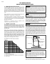
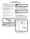
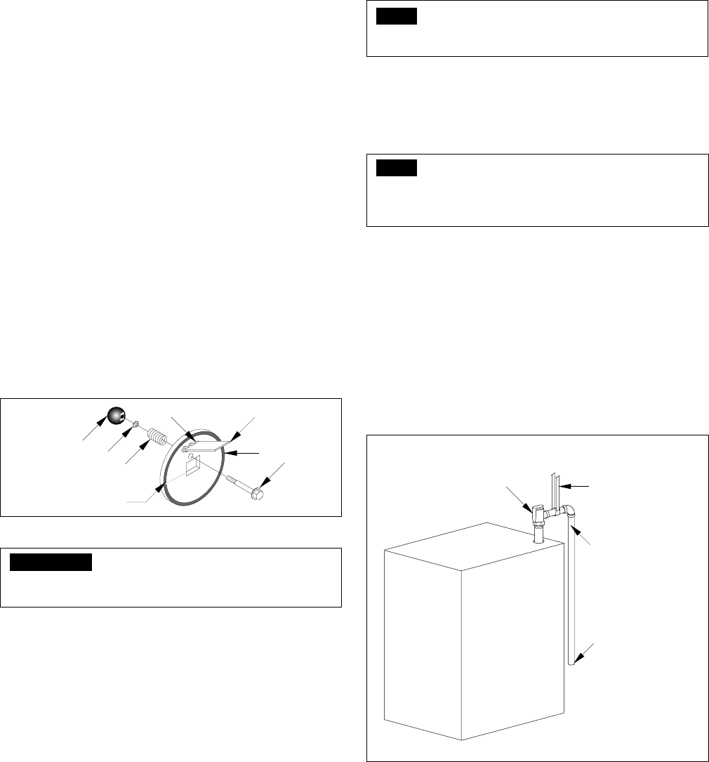
17. SAFETY AND RELIEF VALVES
Safety and relief valves sized on the output rating of each
boiler size are furnished along with the necessary pipe and
fittings for installation in the back section. The valve discharge
connections should be piped to a location where people will
not be exposed to hot vapor or liquid. Any discharge piping
should be supported so as to prevent exerting any strain on
the valve body by the weight of the piping. See FIGURE 10.
FIGURE 10
Some state and local codes require steam safety valves be
piped to the atmosphere outside the building.
13. CLEANOUT COVERS
Be sure the rope seals are in place around the groove in the
cleanout cover plate. Install the plates on the boiler sections
carefully to insure proper sealing all around, using the
5/16" x 2" special anchor bolt and 5/16" hex head nuts. After
periodic flue cleaning, replace nuts at 10 lbs. torque. Use
Hi-Temp silicone caulk to seal covers air-tight.
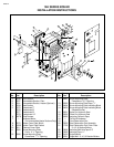
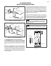
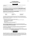
14. REAR OBSERVATION PORTS 7-12 SECTIONS
INSTRUCTIONS FOR ASSEMBLY:
1. Locate steel “flapper door” (Item 6) as shown in FIGURE
9 below. Drive Item 7, “expansion pin”, into hole in Item 1
to secure 6 in position.
2. Lift Item 6 up and install Item 2, “hex bolt”.
3. Slide Item 3, “compression spring” over the hex bolt and
screw Item 4 “hex nut” to hex bolt.
4. Screw Item 5, “ball knob” into position and lock location
using Item 4 as a “jam” nut.
5. Adhere 24-1/2" insulating tape as shown to Item 1.6.
Mount assembly to back section of boiler.
7. 3-6 section boilers use a solid cover which is installed the
same way.
FIGURE 9
IMPORTANT
Item 6 must always be part of the assembly. Check
condition twice a year and replace as needed.
1
2
3
4
5
7
6
INSULATING TAPE
FOR DISCHARGE PIPING THROUGH ROOF CONSULT THE SMITH COMPANY
DISCHARGE PIPE SIZE
TO EQUAL VALVE OUTLET.
DO NOT RESTRICT FLOW.
RELIEF OR SAFETY VALVE
DO NOT REMOVE RATING
OR WARNING TAGS.
SUPPORT DISCHARGE
PIPING SO AS TO AVOID
STRAIN ON VALVE BODY
DISCHARGE SO AS TO
AVOID EXPOSURE OF
PERSONS TO HOT
LIQUID OR VAPOR.
LEAVE OPEN END
VISIBLE FOR PERIODIC
INSPECTION FOR SLOW
LEAKAGE OR DRIPS.