


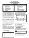
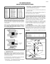
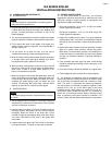

FIGURE 6 — TANKLESS PIPING
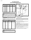
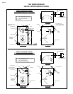
FIGURE 7 — DUAL TANKLESS PIPING
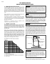
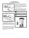
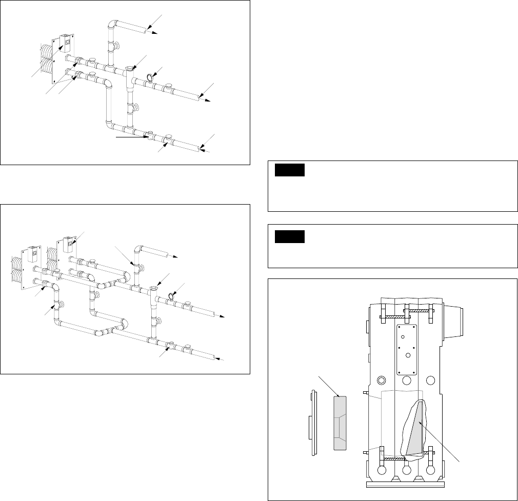
12. BURNER MOUNTING PLATE & TARGET WALL
The new target wall used on 3-6 section boilers must be
positioned with the flat side tight against the rear casting
and with the bottom side resting on the floor of the combustion
chamber. No glues or fasteners are used to secure the target
wall.
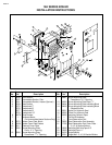
Each boiler is provided with a cast iron burner mounting
plate with an appropriate burner opening and tapped holes
for studs to accommodate burner flange. The mounting plate
is furnished with 1/4" diameter sealing rope and an insulation
block which should be installed on the plate before placing
the plate on the boiler. (See exploded view on page 2, Items
11-13 & FIGURE 8.)
19A SERIES BOILER
INSTALLATION INSTRUCTIONS
PAGE 7
HOT
WATER
SUPPLY
OUT
IN
UNIONS
GATE VALVE
TEMPERING VALVE
FLOW LIMITING VALVE
TEMPERATURE GAUGE
OPERATING
CONTROL
TANKLESS
HEATER
TEMPERED
WATER
SUPPLY
COLD
WATER
INLET
OUT
IN
OUT
IN
GATE VALVE
HOT
WATER
SUPPLY
UNION
GATE VALVE
TEMPERING VALVE
FLOW LIMITING VALVE
TEMPERATURE GAUGE
OPERATING
CONTROL
TANKLESS
HEATER
TEMPERE
D
WATER
SUPPLY
COLD
WATER
INLET
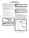
The sealing rope should be placed in the groove on the
boiler side of the plate using adhesive to hold it in place. The
insulation block has a burner opening and a cutout for the
observation opening. Locate the block with the high
temperature facing on the fire side in the opening in the front
section. The burner mounting plate insulating block for
Beckett burners is installed with the dished side facing
towards the combustion chamber.
Attach the block to the plate with the four 1/4" x 5" machine
screws and 1-1/2" O.D. washers, the washers on the insulation
block side. At the time of burner installation, the hole in the
insulation block may have to be enlarged. See separate burner
installation booklet for further assistance and dimensions.
NOTE
Tighten burner mounting plate screws evenly to slightly
compress rope gasket. Overtightening will cause plate
cracking at corners.
NOTE
Most large burners require support to the floor. See burner
manufacturer's manual for such specifications if needed.
FIGURE 8
Insulating Block
Target Wall