


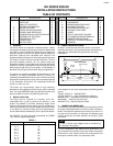

TABLE 5
Feed water makeup requirements.
NOTE
These recommendations are considered normal for
compact buildings on the basis of 80% receiver use.
Where buildings are spread out, additional receiver
capacity may be necessary because of the extended
time required for condensation to return to the receiver.
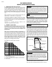
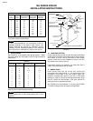
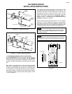
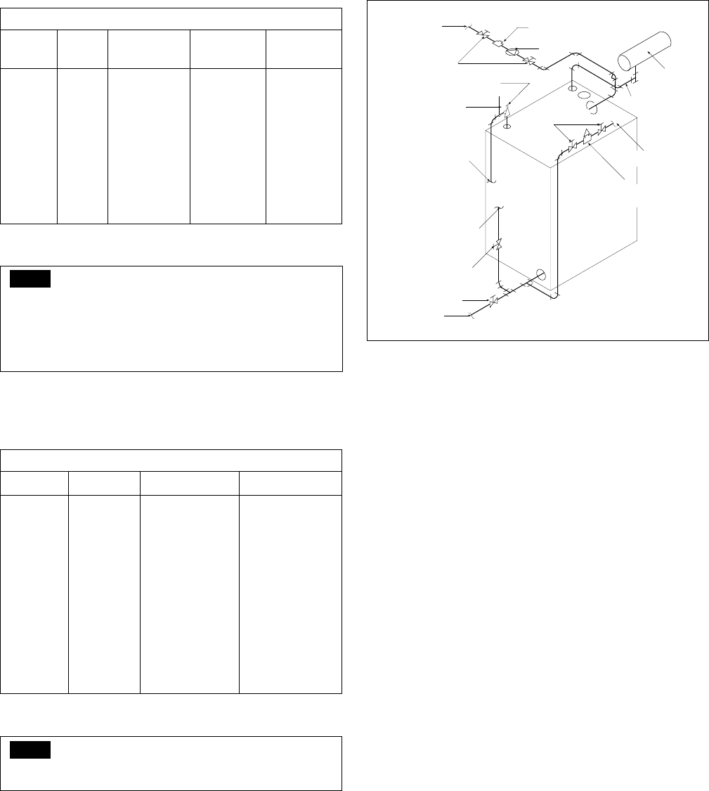
9. WATER PIPING
See FIGURE 5 for acceptable water piping diagram. TABLE
6 gives pumping rate and supply & return sizing for standard
installations.
TABLE 6
Based on 20°F system temperature drop.
NOTE
Boiler supplied with 4" water supply tapping and 3" return
tapping.
FIGURE 5
10. TANKLESS HEATERS
Heater openings are provided for below-the-water-line tankless
heater coils in all special intermediate sections when ordered.
See TABLE 2 for the conr•ct placement of these heater
sections. Install the low limit temperature control in the 3/4"
tap located in the center of the coil.
If the heater sections are installed in an order other than in
TABLE 2 the jacket panels will not match.
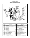
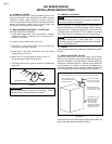
11. SMOKE HOOD
Install smoke hood with the correct size smoke pipe
connecting collar using the 5/16" x 1-1/2" studs and hex nuts
furnished in screw seats in the back section. Apply self-
adhesive insulating tape (Items 21 and 22 in Parts detail
drawing on Page 2) to smoke hood flange and damper angle
Item 23. Fasten the slide damper in the open position for
starting the burner adjustment process.
See FIGURE 6 for recommended “L” coil piping and FIGURE
7 for SM9-18 single and/or dual piping arrangements.
19A SERIES BOILER
INSTALLATION INSTRUCTIONS
PAGE 6
3
4
5
6
7
8
9
10
11
12
.61
.85
1.19
1.52
1.86
2.19
2.53
2.86
3.20
3.53
1.4
1.9
2.4
2.9
3.3
3.8
4.3
4.8
5.2
5.7
1.22
1.70
2.37
3.04
3.71
4.38
5.05
5.72
6.39
7.06
12
16
22
29
35
41
47
54
60
66
NUMBER
OF
SECTIONS
EVAPOR.
RATE
GPM
WATER 1"
BELOW WATER
LEVEL GAL.
MIN. FEED
WATER PUMP
RATE-GPM
CONDENSATE
RECEIVER
CAP.-GAL.
BOILER SIZE GPM RETURN CONN. SUPPLY CONN.
3
4
5
6
7
8
9
10
11
12
30
41
58
74
90
106
123
139
155
171
2"
2"
2-1/2"
3"
3"
3"
3"
3"
3"
3"
2"
2"
2-1/2"
3"
3"
3"
3"
3"
4"
4"
GATE VALVE
SUPPORT RELIEF VALVE
DISCHARGE PIPE
TERMINATE DISCHARGE
PIPE SO AS TO AVOID
DISCHARGE ON PERSONS
SYSTEM RETURN
CONNECTION
BLOWDOWN VALVE
TO DRAIN
GATE VALVE
TYPICAL WATER PIPING DIAGRAM
RELIEF VALVE
PRESSURE
REGULATING
VALVE
GATE
VALVE
CIRCULATOR
EXPANSION
TANK
AIR REMOVAL
PIPING
CHECK VALVE
C.W. MAKEUP
CONNECTION
SYSTEM SUPPLY
CONNECTIONS