


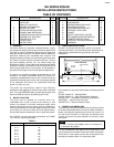

2. Water Boilers – The assembled boiler shall be subjected
to a hydrostatic test pressure not less than 1-1/2 times the
maximum allowable working pressure.
3. The required test shall not exceed the test pressure by
more than 10 PSI.
Excessive torque on draw rods may damage castings. Do
not exceed the torque shown in TABLE 3.
In a cold environment, hydronic seals may not quickly conform
to sealing surfaces when properly compressed. Under such
conditions, hydrostatic testing with cold water might show
weeping or leaking at the seals. To avoid this possibility,
delay filling the boiler with cold water for a few hours after
assembly, or use warm water, if available, for the tests.
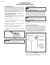
If there is seepage about chaplets or minor leakage, consult
the Smith Company representative for advice regarding
A.S.M.E. Code approved repairs by peening or plugging.
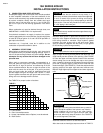
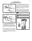
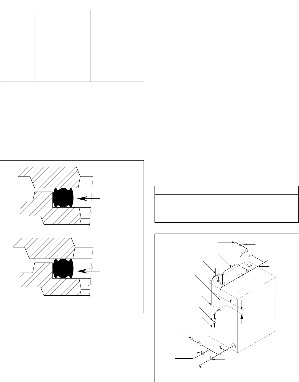
8. STEAM PIPING
A steam piping schedule is shown in TABLE 4. Pitch piping
to allow condensate to flow in the same direction as steam.
Makeup water connections must be made to the return piping,
not directly to the boiler. Install blow-down valves as required.
See FIGURE 4 for recommended acceptable steam piping
arrangement.
TABLE 4
BOILER SIZE NO. OF 3" RISERS HEADER EQUALIZER
3 THRU 5 SECTION 1 3" 1-1/2"
6 THRU 10 SECTION 2 4" 2"
11 AND 12 SECTION 2 5" 2-1/2"
FIGURE 4
19A SERIES BOILER
INSTALLATION INSTRUCTIONS
PAGE 5
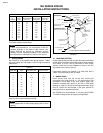
TABLE 3
STEP 1 UPPER RIGHT 5 FT. LBS.
STEP 2 LOWER LEFT 5 FT. LBS.
STEP 3 UPPER LEFT 5 FT. LBS.
STEP 4 LOWER RIGHT 5 FT. LBS.
STEP 5 UPPER RIGHT 25 FT. LBS.
STEP 6 LOWER LEFT 25 FT. LBS.
STEP 7 UPPER RIGHT 50 FT. LBS.
STEP 8 LOWER LEFT 50 FT. LBS.
STEP 9 UPPER LEFT 10 FT. LBS.
STEP 10 LOWER RIGHT 10 FT. LBS.
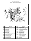
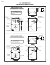
Prepare additional intermediate sections and install in the
same manner described above. Be sure each section is
properly sealed against water leakage and flue gas exfiltration.
Be certain the angle rails remain level and provide support
for each section as it is assembled. Check each section for
vertical position.
When all sections, including the front section or back are in
place, check all draw rods to insure iron-to-iron contact at
ports.
DO NOT APPLY EXCESSIVE TORQUE
. See TABLE
3 for recommended torques.
FIGURE 3
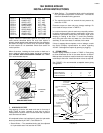
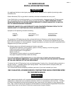
7. HYDROSTATIC TEST
Plug tappings, fill boiler with water and vent air from top of
boiler. Check for leaks. Leakage at seals may be due to
misalignment of hydronic seals. Loosen draw rods, reposition
seals and retest as above.
All completed boilers shall satisfactorily pass the hydrostatic
tests as prescribed by A.S.M.E., Code Section IV.
1. Steam Boilers – The assembled boiler shall be subjected
to a hydrostatic test of not less than 45 PSIG.
HYDRONIC
SEAL
HYDRONIC
SEAL
CORRECT
INCORRECT
SEALING SECTIONS
2" BELOW MINIMUM
BOILER WATER LINE
BOILER WATER LINE
41 1/4" ABOVE FLOOR
STEAM HEADER
STEAM SUPPLY
TO SYSTEM
GATE VALVE
SUPPORT DISCHARGE
PIPE
3" STEAM RISER(S)
EQUALIZER
CONNECTION
TERMINATE DISCHARGE
PIPE SO AS TO AVOID
DISCHARGE ON PERSONS
ALTERNATE RETURN
CONNECTION
C.W. MAKEUP
CONNECTION
GATE VALVE
BLOWDOWN VALVE
TO DRAIN
RETURN
CONNECTION
GATE VALVE
*
*
SAFETY VALVE
TYPICAL STEAM PIPING DIAGRAM