


3. CODES AND REGULATIONS
All work in connection with the boiler, burner and controls
must be performed in strict accordance with requirements of
state and local authorities having jurisdiction over boiler
installations.
FIGURE 1
In the absence of such local requirements, the following should
govern:
A.S.M.E. Section IV - “Heating Boilers"
A.S.M.E. Section VI - “Care and Operation of Boilers”
ANSI/NFPA 31 - “Installation of Oil Burning Equipment”
ANSI/Z223.1 - “National Fuel Gas Code”
ANSI/NFPA 70 - “National Electrical Code”
4. CHIMNEY AND BREECHING
The breeching connection between boiler and chimney should
be as direct as possible with the minimum number of elbows or
bends. It should pitch upwards to the chimney at a rate of 1/4
inch per foot of horizontal run. Generally, the breeching and
chimney should be the same diameter as the boiler outlet
connection.
NOTE
11 and 12 section uses adapter collar for connection to
12" diameter vent system.
For fuel conservation and stable burner performance, the
vent connection from the boiler should not include a barometric
draft control or other opening unless the venting system can
develop an excessive draft, or is required by code.
19A SERIES BOILER
INSTALLATION INSTRUCTIONS
1. GENERAL
19A Series boilers are wet-base, extended surface, vertical
flue design with integral cast flue gas collector for pressurized
firing with oil, gas or combination power burners. Upper and
lower port hydronic seals are of a special material resistant to
petroleum products and compatible with ethylene and
propylene based anti-freeze (non automotive type) which does
not contain corrosion inhibitors to protect aluminum. The flue
gas joints between sections, etc. are sealed using high
temperature (2300°F) ceramic fiber rope. Access to the heating
surface for cleaning is provided from the left hand side of the
boiler through large cast iron cover plates. A slide damper is
provided in the flue gas outlet for back pressure adjustment.
The boilers are supplied completely knocked down for field
assembly, as factory assembled blocks of sections or
completely assembled boiler-burner units. All items should be
inspected for damage upon receipt, and any damage reported
to the wholesaler and trucker. All components should be
stored in a clean, dry area.
The boilers are conservatively rated for high efficiency
performance with capability for down-firing to match connected
load. The large OBROUND upper port provides transfer area
above the water surface for dry steaming at full load.
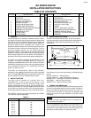
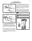
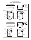
2. BOILER LOCATION
The boiler must be installed on a smooth, level, non-
combustible floor or pad as close to the chimney or vent
location as possible to minimize breeching length. Allow
clearance around the boiler for piping, service, maintenance,
cleaning and tankless coil removal. Approximately 30 inches
on the sides is a minimum (Check local code requirements).
Do not install electrical conductors in floor or pad under boilers.
See FIGURE 1 for boiler floor pad requirements, and TABLE
1 for minimum required pad length.
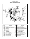
TABLE OF CONTENTS
SECTION DESCRIPTION PAGE SECTION DESCRIPTION PAGE
19A SERIES ISOMETRIC DRAWING 2 10 TANKLESS HEATERS 6
PARTS LIST 2 11 SMOKEHOOD 6
TABLE OF CONTENTS 3 12 BURNER MOUNTING PLATE 7
1 GENERAL INFORMATION 3 13 CLEANOUT COVERS 8
2 BOILER LOCATION 3 14 REAR OBSERVATION PORT 8
3 CODES AND REGULATIONS 3 15 CONTROL LOCATIONS 8
4 CHIMNEY AND BREECHING 3 16 JACKET 8
5 COMBUSTION AND VENTILATION AIR 4 17 SAFETY AND RELIEF VALVES 8
6 ASSEMBLY OF SECTIONS 4 18 CLEANING BOILER WATERWAYS 9
7 HYDROSTATIC TEST 5 19 OWNER'S INSTRUCTIONS 9
8 STEAM PIPING 5 CONTROL TAPPINGS DIAGRAM 10
9 WATER PIPING 6 WARNING 11
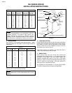
Boiler No. Min. Recommended Pad Length
19-*-3 30"
19-*-4 36"
19-*-5 42"
19-*-6 48"
19-*-7 54"
19-*-8 60"
19-*-9 66"
19-*-10 72"
19-*-11 78"
19-*-12 84"
TABLE 1
PAGE 3
4 5/32" 12 27/32" 12 27/32"
25 21/32"
4 5/32"
34"
32"
JACKET SIDE PANEL
C
L
OF BOILER
FLOOR
OR PAD
1 1/2" x 2 1/2" ANGLES