


1
7
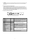
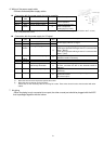
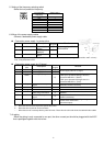
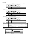
5. Setting of the frequency selecting switch
・Select the ion-production frequency.
Ion-production
frequency
Switch setting
1Hz 0
3Hz 1
5Hz 2
10Hz
3
15Hz 4
20Hz 5
30Hz 6
60Hz 7
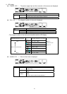
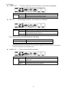
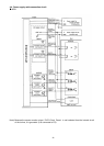
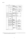
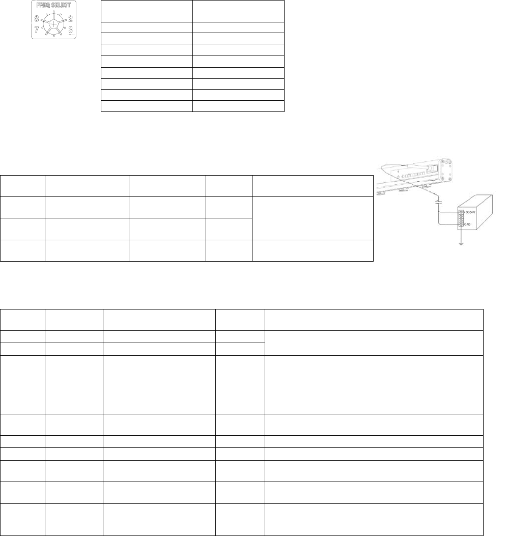
6. Wiring of the power supply cables
・Connect a dedicated power supply cable.
Connection power supply for ionizer drive
No Lead wire color
Description
Direction
of signal
Function
DC1(+)
Brown Power supply
DC24V
○
DC1(-)
Blue Power supply
GND[FG]
○
power supply cable for
ionizer drive
OUT4 Dark Green Sensor monitor
output
- -
※ Be sure to ground DC1(-)[Blue]. (Resistance between the lead wire and the earth ground should be 100Ω or less.)
If not, it may break the ionizer.
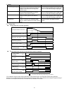
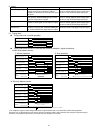
Connection power supply for I/O signal
No Lead wire
color
Description
Direction
of signal
Function
DC2(+)
Red Power supply DC24V
○
DC2(-)
Black Power supply GND
○
Power supply cable for I/O signal
IN1 Light
Green
Discharge-stop signal
○
Signal for starting/ stopping the discharge
(NPN spec)Operation will begin when it is
connected with DC2(-)[Black].
(PNP spec)Operation will begin when it is
connected with DC2(+)[Red].
IN2 Gray Maintenance start-up
signal
△
A signal that is input when the maintenance of the
electrode needle is necessary.
-
White
- - -
-
Orange
- - -
OUT1 Pink Completion signal for
static charge elimination
△
Outputs when the dirt on the electrode needle is
detected.
OUT2 Yellow Maintenance output
signal
△
Outputs when the maintenance of the electrode
needle is necessary.
OUT3 Purple Signal for failure
△
Outputs in case of abnormal high voltage and
sensor and/or CPU failure.
(B contact output)
○ : Wires that are minimum required to operate the ionizer.
△ : Wires that are required to use the functions.
- : Wires that are not necessary with the pulse DC mode. These wires should not be short-circuited with other cables.
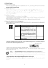
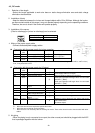
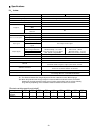
7. Air piping
・When the piping is only connected to one port, the other unused port should be plugged with the M-5P
that is packaged together with the ionizer.
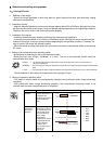
DC Power supply
Brown
Blue
Ground