


VI
CTORY VSPH Models
23
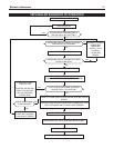
To reset the lockout condition: Turn down thermostat or turn
power off at disconnect switch for at least 45 seconds, then
restore power or set thermostat at desired setting.
Automatic reset: After one hour (1/2 hour for flame failure),
control will automatically retry.
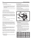
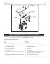
SAFETY CHECK
1. Checking for gas leaks:
Using soap solution, check for gas leaks from meter to
gas v
alve including all pipes and fittings, gas valve con-
nections, manifold and pilot burner gas line and its fittings.
Use liquid soap solution for all gas testing. DO NOT use
open flame.
2. High limit control (Aquastat) test:
Set room ther
mostat high enough for boiler water temper-
ature to reach high limit setting. When this temperature is
reached, the high limit switch should open. Pilot and main
gas valve should close. Inducer starts 15 seconds post-
purge period. POWER and TSTAT/CIRC LED’s will stay
on.
3. Thermostat test:
Set ther
mostat setting to low enough to end call for heat.
Pilot and main gas valve should close circulator off and
inducer will star
t 15 seconds post-purge. POWER LIMIT
and PRESS SWITCH LED’s will stay on during post-
purge
. After the post-purge period, POWER and LIMIT
LED’s stay on.
4. Control safety shutdown test:
With main burners firing (all LED’s on) disconnect igni-
tion/sensor cable from boiler control. Gas valve should
shut off burners, FLAME LED starts flashing.
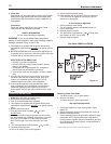
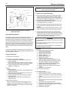
5.
Pressure switch test:
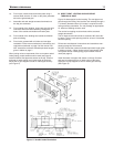
With burners firing, remove plastic hoses from pressure
s
witch or from aluminum tubing (see Figure 21), gas valve
must shut off, PRESS SWITCH LED starts flashing.
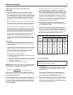
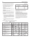
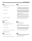
POWER LED * 120 V power supply. Polarity is reversed Reverse Hot and NEUTRAL wires in the junction
box.
POWER + TSTAT/CIRC LED’S * 48 VAC on thermostat circuit. Check and correct the thermostat or zone valves
wirings.
POWER + PRES SWITCH LED’S * Pressure switch contacts are closed prior to Check air pressure switch.
energizing the blower motor or does not close Check hose connections to pressure switch.
within 5 minutes of the blower being turned on. Check for obstruction/restriction in venting, air
intake piping and termination.
POWER + FLAME LED’S * Flame sensed without call for heat. Remove air box front panel.
Turn off power for at least 45 seconds.
Check if pilot flame exists during pre-purge
period (first 30 seconds). If pilot flame exists,
replace gas valve
FLAME LED * Pilot flame was not established during trial for Check gas valve knob to be in “ON” position.
ignition. Check inlet gas pressure.
Check pilot gas line.
Check ignition cable and the connections.
Check pilot flame to be 3/8” to 1/2" long
PRES SWITCH LED Pressure switch opened during boiler run Check pressure switch and its hoses.
period. Wind gusts over 40 mph. Check for obstruction in venting, air intake
piping and ter
mination.
L
ED’s FLASHING
INDICATION
B. DIAGNOSTIC FLASH CODES
Flashing LED’s provide diagnostic information
WARNING: Only a trained, experienced service technician should perform troubleshooting. Turn off all electric power to
t
he boiler before service
R
EMEDY
* Control Lockout
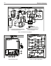
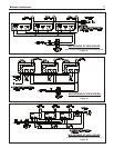
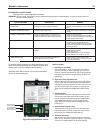
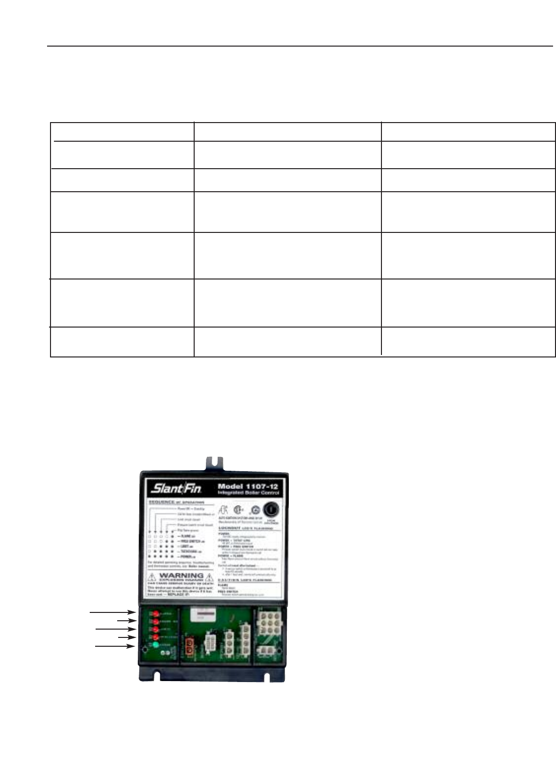
Figure 20. Integrated boiler control.
Flame LED (Red)
Pressure Switch LED (Red)
Hi Limit LED (Red)
Thermostat/Circ. LED (Red)
Power LED (Green)