


VI
CTORY VSPH Models
15
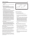
VENTING AND AIR INTAKE SYSTEM REGULAR
INSPECTION
A
. Inspect the system regularly for condensation, corrosion
a
nd/or physical damage. A qualified professional should ser-
vice the boiler annually and include such an inspection at that
time.The homeowner should look over the system monthly for
d
amage, water stains, any signs of rust, other corrosions or
separation of the vent and air intake piping (if direct-vent).
B. Should an inspection turn up signs of condensation, corrosion
or damage, the boiler should be shut down immediately and
t
he condition should be corrected by a qualified professional.
C. All Victory VSPH boilers are equipped with a built-in conden-
sation drain and trap.The trap loop must be filled with water.
DO NOT operate the boiler without filling the trap with water to
prevent flue gas discharge into space. Periodic inspection
should be made of this assembly for deterioration of the tub-
ing and to insure that the trap is not plugged. If it is plugged or
appears to have excessive sediment in it, it should be
removed from the drain assembly, straightened out to clear
the obstruction, reformed, filled with water and reinstalled as
before.
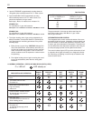
GAS PIPING
A. Local installation codes apply. The pipe joint compound
used on threads must be resistant to the action of liquefied
petroleum gases.
B. The gas supply line to the boiler should run directly from the
meter for natural gas or from the fuel tank for L.P. propane
gas. See page 2 for location of union and manual main
shut-off valve that may be specified locally.
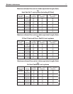
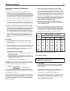
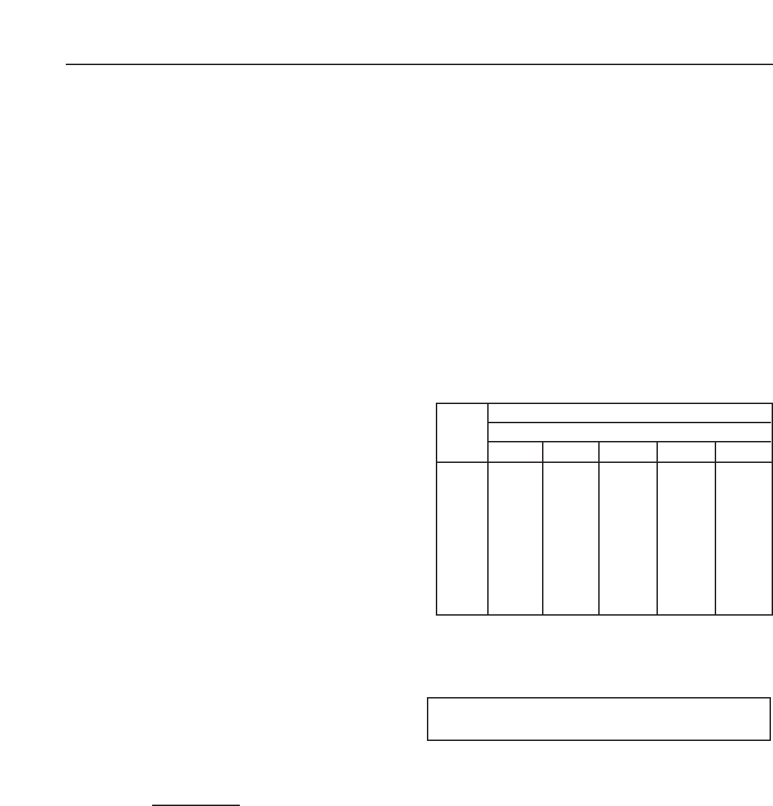
Selecting pipe size for natural gas:
1. Measure or estimate the length of piping from the meter
to the installation site.
2. Consult gas supplier for heating value of gas (Btu/cu. ft.).
3. Divide boiler rated input by heating value to find gas flow
in piping (cu. ft. per hour).
4. Use table below to select proper pipe size.
EXAMPLE: Boiler model VSPH-150 is to be installed. Distance
from gas meter to the boilers is 30ft. Heating value of natural
gas is 1020 Btu/cu. Ft. Select proper pipe size.
Gas flow = 150,000 Btu/hour
= 147 cu. ft. per hour
1020 Btu/cu. ft.
At 30 ft. length of pipe, match required capacity from table on
this page (choose higher capacity, in this case is 152 cu. ft. per
hour). Required pipe size is
3
⁄4".
Improper gas pipe sizing will result in pilot flame outages, insuf-
ficient heat and other installation difficulties. For more informa-
tion and also if other appliances are to be attached to the pip-
ing system, see Appendix C of National Fuel Gas Code ANSI
Z223.1-latest edition.
C. The boiler and its gas connection must be leak tested
before placing the boiler in operation. Use liquid soap solu-
tion for all gas leak testing. DO NOT use open flame.This
boiler and its individual shutoff valve must be disconnected
f
rom the gas supply piping system during any pressure test-
ing of that system at test pressures in excess of
1
⁄2 PSIG.
This boiler must be isolated from the gas supply piping sys-
t
em by closing its individual manual shutoff valve during any
pressure testing of the gas supply piping system at test
pressures equal to or less than
1
⁄2 PSIG.
D. All gas piping used should be inspected thoroughly for
cleanliness before makeup. A sediment trap must be provid-
e
d, as illustrated on page 2.
E. The minimum and maximum gas supply pressure (at the
inlet of gas valve) are shown on the boiler rating plate for
the type of gas used. Gas supply pressure should never be
less than minimum or more than maximum pressure when
the boiler or any other appliance is turned on or off.
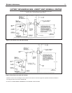
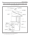
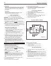
ELECTRICAL WIRING
DANGER:
Before wiring always turn off electric power supply
otherwise, shock or death can result.
1. Power Supply
A separately fused circuit is recommended. Use standard
15 Amp. fuse or breaker and 14 gage conductors in BX
cable or conduit.
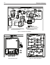
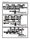
Provide disconnect means and overload protection as
required. See boiler wiring diagram (Figure 13a) boiler con-
trol (Figure13b) and ladder diagram (Figure 13c).
Boiler must be electrically grounded in accordance with the
requirements of the authority having jurisdiction, or, in the
absence of such requirements, with the National Electrical
Code, ANSI/NFPA 70-latest edition.
Length
of pipe
in Feet
1/2
3
/4 11
1
/4
1
1
/2
Gas Flow In piping -- cu. ft. per hr.
Iron Pipe Size (IPS) — inches
10 132 278 520 1050 1600
20 92 190 350 730 1100
30 73 152 285 590 890
40 63 130 245 500 760
50 56 115 215 440 670
60 50 105 195 400 610
70 46 96 180 370 560
80 43 90 170 350 530
90 40 84 160 320 490
100 38 79 150 305 460
At pressure drop of 0.3 in.
w
ater, specific gravity = 0.6.