


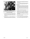
HARNESS CONNECTION
General
Splicing of wire leads is necessary in the installation of the
garage door opener to the vehicle. Find the instructions for a
specific model in the sections that follow, and refer to the ser-
vice manual appendix for proper wire splicing procedures.
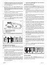
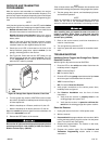
Be sure to follow manufacturer's instructions when using
the UltraTorch UT-100 or any other radiant heating device.
Failure to follow manufacturer's instructions can cause a
fire, which could result in death or serious injury. (00335a)
• Avoid directing heat toward any fuel system component.
Extreme heat can cause fuel ignition/explosion resulting
in death or serious injury.
• Avoid directing heat toward any electrical system com-
ponent other than the connectors on which heat shrink
work is being performed.
• Always keep hands away from tool tip area and heat shrink
attachment.
For 2011 and later Softail models: Proceed to the following
section.
For Touring and Trike models: Proceed to that section.
For ALL OTHER models: Proceed to Black Lead Connection
for the specific model.
2011 and Later Softail Models
NOTES
Requires separate purchase of Electrical Connection Harness
(H-D Part No. 72673-11).
Electrical connectors are identified in the service manual by
the number and letter shown here within brackets.
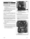
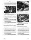
1. Locate the Digital Technician connector [91A] (a gray six-
way Deutsch pin connector with a rubber boot) under the
seat. Place the Electrical Connection Harness at connector
[91A], but DO NOT connect at this time.
2. Route the garage door opener wires over to the Electrical
Connection Harness. Remove the orange/white wire from
the conduit. Cut the orange/white and black wires to a
suitable length to easily reach the sealed splice connectors
on the Electrical Connection Harness. DO NOT cut the
yellow or white wires.
3. Splice the black garage door opener wire to the black
wires in the Electrical Connection Harness.
4. Splice the orange/white garage door opener wire to the
red/yellow wires in the Electrical Connection Harness.
5. Use a heat gun or suitable radiant-heating device to shrink
the connector to the wires.
6. Use the heat gun or heating device to seal the open end
of the sealed splice connector on the red/blue wires in
the Electrical Connection Harness.
7. Pull the rubber boot out from the gray Digital Technician
pin connector [91A]. Cut the boot off of the wires.
8. Connect the socket housing of the Electrical Connection
Harness to connector [91A].
9. Insert the rubber boot into the open pin connector of the
Electrical Connection Harness.
10. Loosen or remove the four screws holding the ECM to the
mounting bracket. Route the Electrical Connection Harness
under the ECM connector. Tighten the four screws to
45-55 in-lbs (5.1-6.2 Nm).
11. Proceed to the Yellow and White Lead Connections
section for the specific model.
Touring and Trike Models
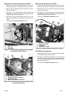
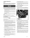
1. Cut the yellow, white and orange/white transmitter wires
to about the same length as the transmitter black ground
wire. Cut to allow enough wire to easily strip and splice
the wires.
1
3
2
4
is06725
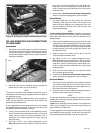
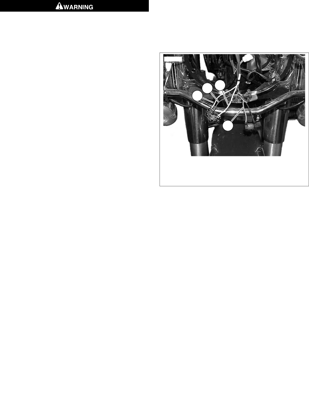
1. Black (ground) wire
2. Yellow wire
3. White wire
4. Orange/white wire
Figure 14.Wires for Transmitter Connections (FLHR)
2. FLHR Touring Models: See Figure 14. Cut the yellow
(2), black (1) and white (3) headlamp wires inside the
nacelle, staggering the lengths a bit to avoid all three
splices being together.
FLHT and FLHX Touring and Trike Models: See Figure
9. Cut the yellow (6), black (4) and white (5) headlamp
wires inside the fairing, staggering the lengths a bit to
avoid all three splices being together.
FLTR Touring Models: See Figure 10. Cut the yellow
(6), black (4) and white (5) headlamp wires inside the
fairing, staggering the lengths a bit to avoid all three
splices being together.
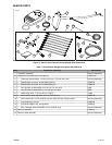
ALL Touring/Trike Models: Slide the woven wire conduit
from the kit (see Figure 27, Item 9) over all three headlamp
wires.
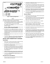
3. See Figure 15, the 2 into 1 splice configuration. Use a red
sealed splice connector (Figure 27, Item 4) from the kit to
splice the black garage door opener transmitter wire to
the black wires from the headlamp. Trim back the trans-
mitter wire harness casing as needed to assist splicing.
-J02028 7 of 16