1. Headlamp connector [38]
Figure 23.Wire Splice Locations (2005 and Later V-Rod)
YELLOW AND WHITE LEAD CONNECTIONS
TO HEADLAMP
Dyna Models
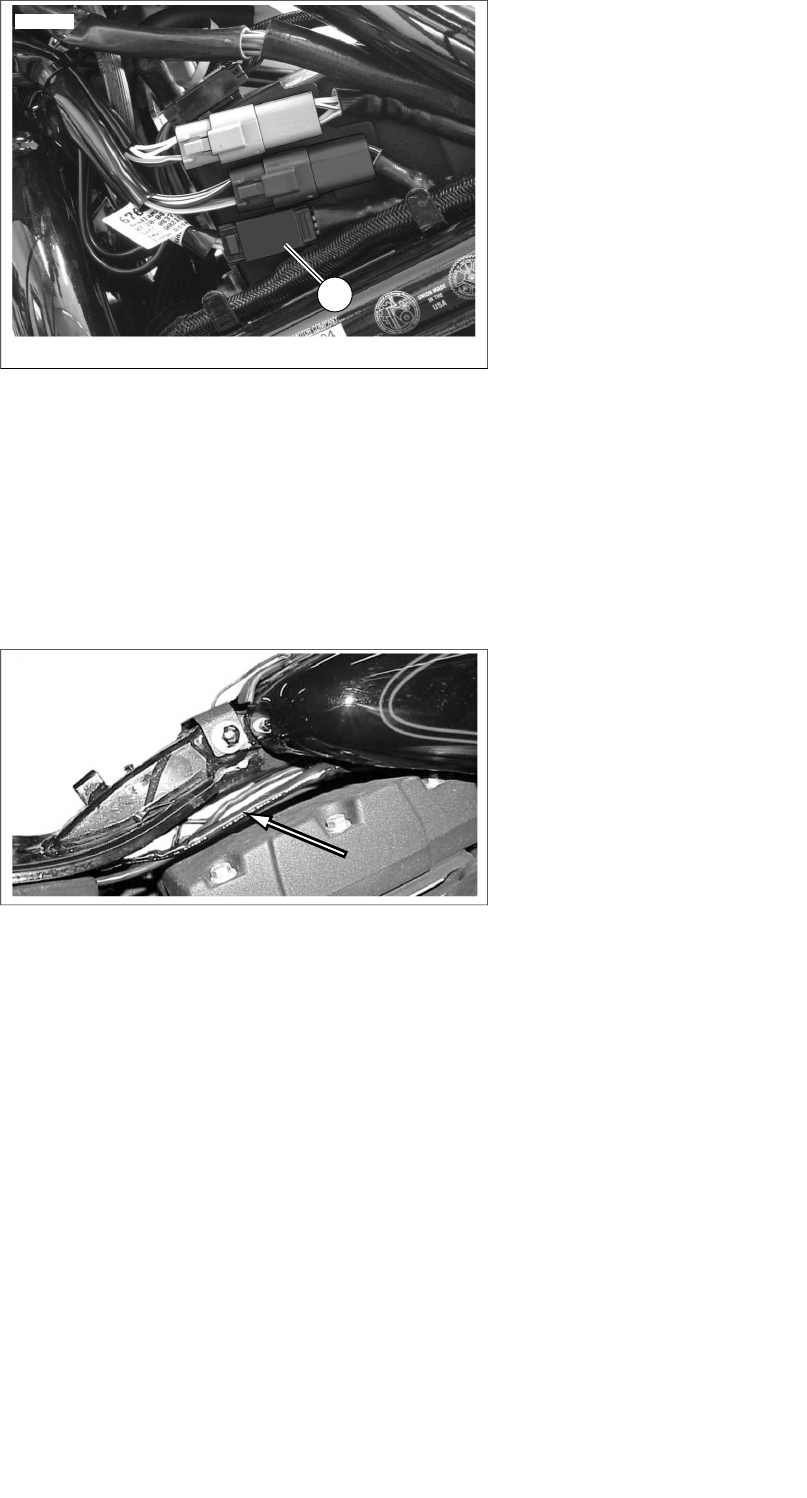
1. See Figure 24. Use cable straps from the kit to fasten the
remaining transmitter wires (yellow and white) and conduit
to the motorcycle wires leading to the headlamp. Lift the
fuel tank as needed to feed the wires under the tank and
toward the headlamp.
Figure 24.Transmitter Wire Routing to Headlamp (Dyna)
2. Route the wires into the headlamp housing through the
grommet on the lower rear of the housing.
NOTE
To route the transmitter wires through the grommet, push a
hooked piece of wire through the grommet from the inside of
the headlamp housing.
A light coat of liquid soap, window cleaner or all-purpose lub-
ricant may be needed to pull the wires back through the
grommet with the hooked wire.
In some applications the transmitter wires may not fit through
the headlight housing grommet. In that case, the wires must
be spliced outside the headlamp housing.
3. Cut the yellow and white wires in the headlamp housing
several inches from the headlamp connector. Cut excess
length from the yellow and white transmitter wires if
necessary. Cut to allow enough wire to easily strip and
splice the wires.
4. See Figure 15, the 1 into 1 splice configuration. Use a
blue sealed splice connector (Figure 27, Item 5) from the
kit to splice the white transmitter wire to the white head-
lamp wires. Use the remaining blue sealed splice con-
nector to splice the yellow transmitter wire to the yellow
headlamp wires.
5. Proceed to the Receiver and Transmitter Programming
section to program the garage door opener controls.
Softail Models
1. Use cable straps from the kit to fasten the remaining
transmitter wires (yellow and white) and conduit to the
motorcycle wires leading to the headlamp. Lift the fuel
tank as needed to feed the wires under the tank and
toward the headlamp.
NOTE
For 2011 and later Softail models, the headlamp circuit wires
in the vehicle harness are blue with a white or yellow tracer,
rather than solid white and solid yellow as described in the
following steps.
2. Cut the yellow and white wires in the main vehicle harness
headlamp circuit at an accessible point. Cut excess length
from the yellow and white transmitter wires if necessary.
Trim back the transmitter wire harness casing as needed
to assist splicing. Cut to allow enough wire to easily strip
and splice the wires.
3. Slide the woven wire conduit (9) from the kit over the
yellow and white transmitter wires.
4. See Figure 15, the 1 into 1 splice configuration. Use a
blue sealed splice connector (Figure 27, Item 5) from the
kit to splice the white transmitter wire to the white head-
lamp wires. Use the remaining blue sealed splice con-
nector to splice the yellow transmitter wire to the yellow
headlamp wires.
5. Slide the woven wire conduit over the yellow and white
wire connections after splicing.
6. Proceed to the Receiver and Transmitter Programming
section to program the garage door opener controls.
Sportster Models
1. Route the remaining transmitter wires (yellow and white)
and conduit through the top of the frame under the fuel
tank and up to the headlamp. Use cable straps from the
kit to fasten the wires to the harness.
2. Route the wires into the headlamp housing through the
grommet on the lower rear of the housing.
NOTE
To route the transmitter wires through the grommet, push a
hooked piece of wire through the grommet from the inside of
the headlamp housing.
A light coat of liquid soap, window cleaner or all-purpose lub-
ricant may be needed to pull the wires back through the
grommet with the hooked wire.
In some applications the transmitter wires may not fit through
the headlight housing grommet. In that case, the wires must
be spliced outside the headlamp housing. See Figure 25.
-J02028 12 of 16


