


1
1
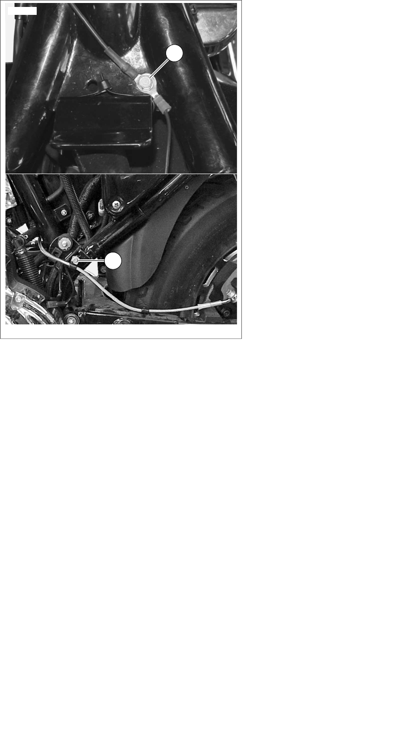
is01103
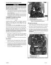
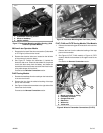
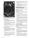
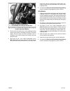
1. Ground screws (black wire)
Figure 16. Ground Connections (Sportster Models)
2002-2003 V-Rod Models
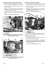
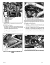
1. Cut the black transmitter ground wire to within easy reach
of one of the ground screws located on the engine cam
covers. Remove the ground screw.
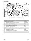
2. See Figure 27. Select the 1/4 in. (6.4 mm) ring terminal
(7) from the kit. Crimp the ring terminal onto the black
transmitter wire per the Packard crimping tool instructions
in the service manual appendix.
3. Fasten the ring terminal to the engine with the ground
screw, and secure per the torque specification in the ser-
vice manual.
4. Proceed to the Orange/White Lead Connection section
for the specific model.
2004 and Later V-Rod Models
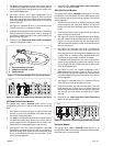
1. See Figure 15, the 2 into 1 splice configuration. Use a red
sealed splice connector (Figure 27, Item 4) from the kit to
splice the black wire (13) from the kit to the black trans-
mitter ground wire according to the instructions in the
service manual appendix.
Slip the conduit (10) from the kit over the spliced ground
wire.
2. Route the ground wire and conduit along the motorcycle
frame to the left of the air box, next to the main harness
to a location under the left-side louvered cover.
3. Cut the black transmitter ground wire and conduit to within
easy reach of one of the ground studs located on each
end of the battery ground cable.
4. Select the 1/4 in. (6.4 mm) ring terminal (7) from the kit.
Crimp the ring terminal onto the black transmitter wire per
the Packard crimping tool instructions in the service
manual appendix.
5. Fasten the black wire ring terminal to the negative terminal
mounting post on the battery.Tighten the terminal fastener
to 60-96 in-lbs (7-10 Nm).
6. Proceed to the Orange/White Lead Connection section
for the specific model.
ORANGE/WHITE LEAD CONNECTION TO
SWITCHED POWER SOURCE
Use the service manual wiring diagrams for a specific model
and year vehicle to locate a power source that is fed through
the ignition switch.
2003 and Earlier Dyna Models
The garage door opener switched power source is an
orange/white (O/W) main harness power lead under the seat
or inside the side cover.
1. Remove the electrical side cover, located on the left side
of the motorcycle near the battery.
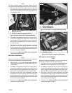
2. See Figure 2. Carefully slice open an area of the main
harness wrap under the seat or inside the side cover at
an accessible point, and cut an orange/white main harness
power lead.
3. Pull only the orange/white wire out of the longer piece of
conduit on the garage door opener wire harness. Cut the
excess length from the orange/white wire to within easy
reach of the cut orange/white wires on the main vehicle
harness.
4. See Figure 15, the 2 into 1 splice configuration. Use a red
sealed splice connector (Figure 27, Item 4) from the kit to
splice the garage door opener wire harness power lead
to the main harness orange/white wires per the instructions
in the service manual appendix.
5. Proceed to the Yellow and White Lead Connections
section for the specific model.
2004 and Later Dyna Models
The garage door opener switched power source is an open
fuse position on the fuse panel. See the FUSES section of the
service manual and the correct wiring diagram in the service
manual appendix.
1. Remove the electrical side cover, located on the left side
of the motorcycle near the battery, by firmly grasping both
sides and pulling outward.
2. Remove the electrical panel from the vehicle per service
manual instructions.
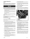
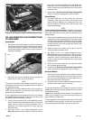
3. See Figure 27. Get the orange/white fuse block adapter
wire (12) from the kit. Note the terminal on each end (see
Figure 17). Only the terminal with the spring tabs will fit
into this fuse block. Carefully cut the unused terminal from
the wire and discard it.
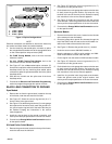
4. See Figure 18. Locate the fuse cavity (1) indicated as
"OPEN" on the fuse block cover in the right fuse block.
Insert the terminal on the orange/white adapter wire until
it stops. Refer to a nearby factory installed terminal for
comparison to verify proper orientation and depth.
-J02028 9 of 16