


5. Pull only the orange/white wire out of the longer piece of
conduit on the garage door opener wire harness. Cut the
excess length from the orange/white wire to within easy
reach of the adapter wire.
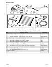
6. See Figure 15, the 1 into 1 splice configuration. Use a
blue sealed splice connector (Figure 27, Item 5) from the
kit to splice the garage door opener wire harness power
lead to the adapter wire per the instructions in the service
manual appendix.
7. See Figure 27. Install the 2A fuse (11) from the kit into the
"OPEN" fuse cavity to complete the circuit.
8. Install the electrical panel per the instructions in the service
manual. Install the electrical panel cover by aligning the
pins with the rubber bushings in the electrical panel and
pushing firmly into place.
9. Proceed to the Yellow and White Lead Connections
section for the specific model.
2
3
1
is02589
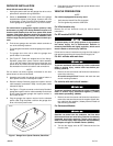
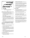
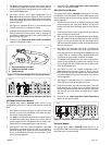
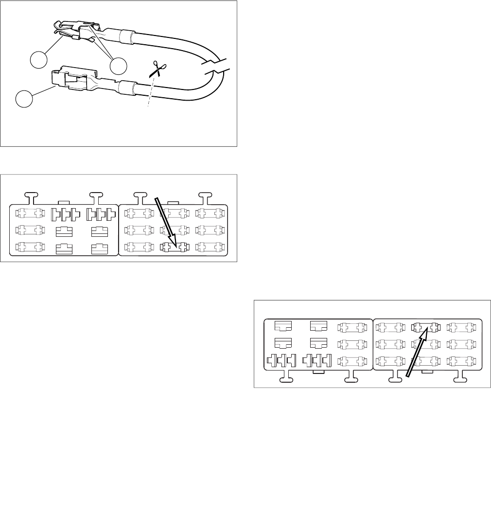
1. CUT this terminal from wire
2. LEAVE this terminal on wire
3. Spring tabs (2)
Figure 17. Fuse Block Adapter Wire (Dyna and Softail)
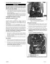
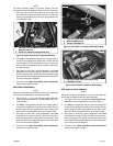
is06515
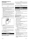
Figure 18. "OPEN" Fuse Block Cavity (2004 and Later Dyna)
2003 and Earlier Softail Models
The garage door opener switched power source is the
orange/white (O/W) wire in the tail lamp harness under the
seat.
1. See Figure 2. Carefully slice open an area of the tail lamp
harness (1) wrap at an accessible point under the seat,
and cut the orange/white wire.
2. Pull only the orange/white wire out of the longer piece of
conduit on the garage door opener wire harness. Cut the
excess length from the orange/white wire to within easy
reach of the cut orange/white wires under the seat.
3. See Figure 15, the 2 into 1 splice configuration. Use a red
sealed splice connector (Figure 27, Item 4) from the kit to
splice the garage door opener wire harness power lead
to the cut orange/white wires per the instructions in the
service manual appendix.
4. Proceed to the Yellow and White Lead Connections
section for the specific model.
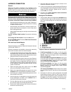
2004-2010 Softail Models
The garage door opener switched power source is an open
fuse position on the fuse panel. See the FUSES section of the
service manual and the correct wiring diagram in the service
manual appendix.
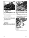
1. Remove the fuse block cover. Remove the two hex head
screws fastening the fuse block bracket, and pull the
bracket and fuse block assembly away from the vehicle
frame.
2. Press the tab retaining the left fuse block, and slide the
block out of the mounting slots.
3. See Figure 27. Get the orange/white fuse block adapter
wire (12) from the kit. Note the terminal on each end (see
Figure 17). Only the terminal with the spring tabs will fit
into this fuse block. Carefully cut the unused terminal from
the wire and discard.
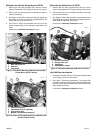
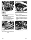
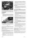
4. See Figure 19. Locate the fuse cavity (1) indicated as
"P&A IGN" on the fuse block cover in the right fuse block.
Insert the terminal on the orange/white adapter wire until
it stops. Refer to a nearby factory installed terminal for
comparison to verify proper orientation and depth.
5. Pull only the orange/white wire out of the longer piece of
conduit on the garage door opener wire harness. Cut the
excess length from the orange/white wire to within easy
reach of the adapter wire.
6. See Figure 15, the 1 into 1 splice configuration. Use a
blue sealed splice connector (Figure 27, Item 5) from the
kit to splice the garage door opener wire harness power
lead to the adapter wire per the instructions in the service
manual appendix.
7. See Figure 27. Install the 2A fuse (11) from the kit into the
"P&A IGN" fuse cavity to complete the circuit.
8. Slide the fuse block into the mounting slots in the fuse
block bracket until it clicks firmly into place. Install the
bracket and fuse block assembly into position and fasten
with the two hex head screws removed earlier. Tighten
securely.
9. Proceed to the Yellow and White Lead Connections
section for the specific model.
is06516
Figure 19. "P&A IGN" Fuse Block Cavity (2004-2010 Softail)
Sportster Models
The garage door opener switched power source is an
orange/white (O/W) main harness power lead inside the elec-
trical side cover or under the seat.
-J02028 10 of 16