NOTE
On some Sportster models the ignition module must be
removed to access the orange/white wire in the main harness.
1. See Figure 20. Carefully slice open an area of the main
harness wrap inside the electrical side cover or under the
seat at an accessible point, and cut an orange/white main
harness power lead.
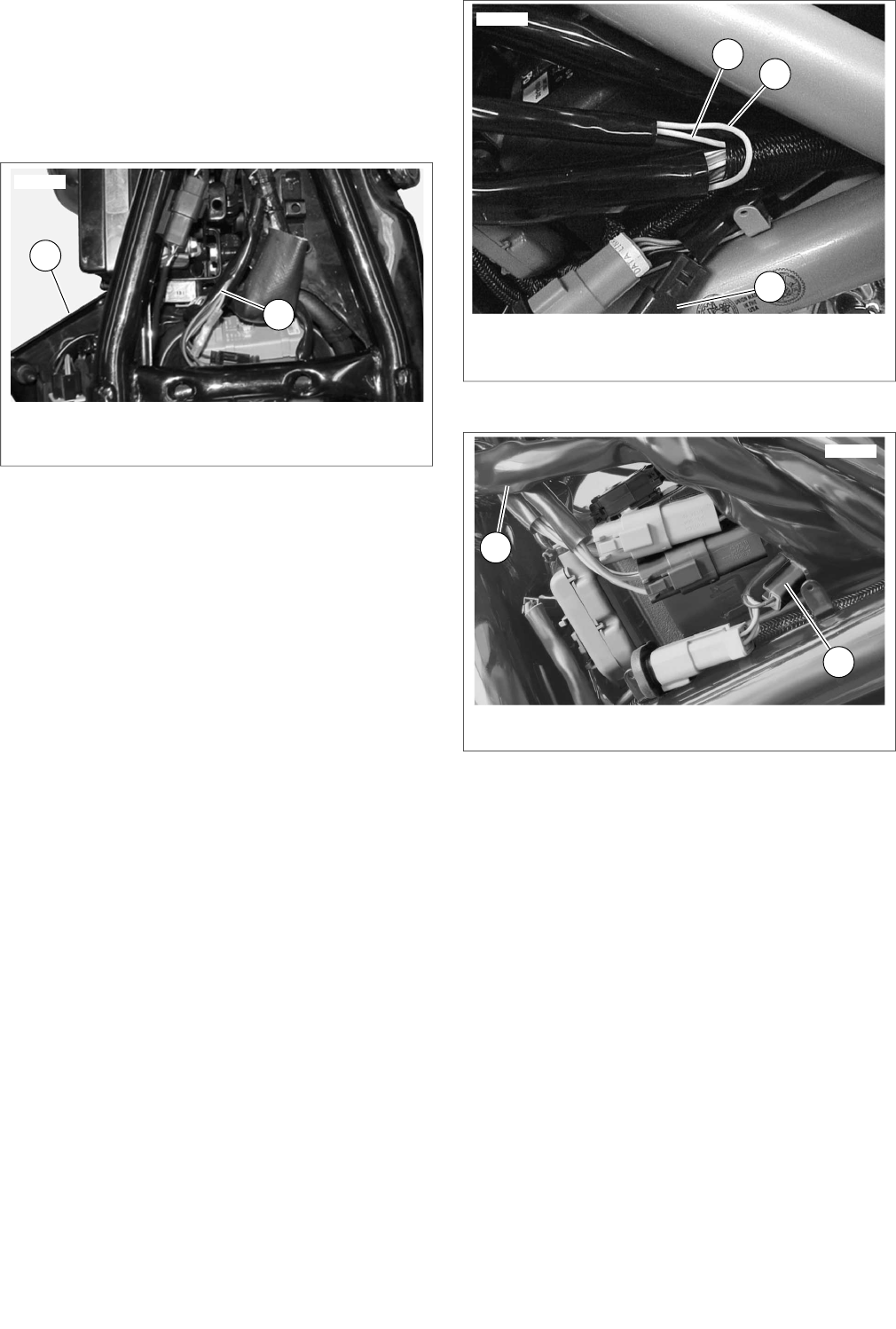
1. Left side cover containing circuit breaker silver
terminal (red wire)
2. Stock wire harness (orange/white wire)
Figure 20. Power Connections (Sportster Models)
2. Pull only the orange/white wire out of the longer piece of
conduit on the garage door opener wire harness. Cut the
excess length from the orange/white wire to within easy
reach of the cut orange/white wires inside the side cover
or under the seat.
3. See Figure 15, the 2 into 1 splice configuration. Use a red
sealed splice connector (Figure 27, Item 4) from the kit to
splice the garage door opener wire harness power lead
to the main harness orange/white wires per the instructions
in the service manual appendix.
4. Proceed to the Yellow and White Lead Connections
section for the specific model.
2002-2004 V-Rod Models
NOTE
Electrical connectors are identified in the service manual by
the number and letter shown here within brackets.
1. See Figure 21 or Figure 22. Cut the orange/white main
vehicle harness wire near the unused position lamp con-
nector [29A] (1).
2. Pull only the orange/white wire out of the longer piece of
conduit on the garage door opener wire harness. Cut the
excess length from the orange/white wire to within easy
reach of the cut orange/white wires at connector [29A].
3. See Figure 15, the 2 into 1 splice configuration. Use a red
sealed splice connector (Figure 27, Item 4) from the kit to
splice the garage door opener wire harness power lead
to the main harness orange/white wires per the instructions
in the service manual appendix.
4. Proceed to the Yellow and White Lead Connections
section for the specific model.
1. Connector [29A] with orange/white wire
2. White headlamp wire
3. Yellow headlamp wire
Figure 21.Wire Splice Locations (2002-2003 V-Rod)
1. Connector [29A] with orange/white wire
2. Headlamp harness
Figure 22.Wire Splice Locations (2004 V-Rod)
2005 and Later V-Rod Models
NOTE
Electrical connectors are identified in the service manual by
the number and letter shown here within brackets.
1. See Figure 23. Cut the orange/white main vehicle har-
ness wire near the headlamp pin connector [38A] (1).
2. Pull only the orange/white wire out of the longer piece of
conduit on the garage door opener wire harness. Cut the
excess length from the orange/white wire to within easy
reach of the cut orange/white wires at connector [38A].
3. See Figure 15, the 2 into 1 splice configuration. Use a red
sealed splice connector (Figure 27, Item 4) from the kit to
splice the garage door opener wire harness power lead
to the main harness orange/white wires per the instructions
in the service manual appendix.
4. Proceed to the Yellow and White Lead Connections
section for the specific model.
-J02028 11 of 16


