


1
2
3
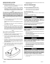
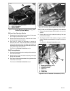
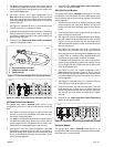
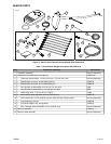
is02055a
1. 1 into 1 splice
2. 2 into 1 splice
3. 3 into 1 splice
Figure 15. Splice Configurations
NOTE
Electrical connectors are identified in the service manual by
the number and letter shown here within brackets.
4. Use the remaining red sealed splice connector to splice
the orange/white transmitter wire to the orange/white wire
on the unused position lamp connector [29B]:
• For FLHR Touring Models, tied to the main harness
inside the nacelle.
• For ALL OTHER Touring/Trike Models, tied to the
interconnect harness near the headlamp.
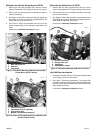
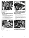
5. See Figure 27. Use a blue sealed splice connector (5)
from the kit to splice the white transmitter wire to the white
headlamp wires. Use the remaining blue sealed splice
connector to splice the yellow transmitter wire to the yellow
headlamp wires.
6. Slide the wire conduit over the splice area of the three
headlamp wires.
7. Proceed to the Receiver and Transmitter Programming
section to program the garage door opener controls.
BLACK LEAD CONNECTION TO GROUND
Dyna Models
1. Remove the nut from the ground stud, located on the top
of the frame, under the seat near the fuel tank.
2. See Figure 27. Select the correct ring terminal (6 or 7)
from the kit to fit the ground stud.
3. See Figure 2. Cut the black ground wire (2) on the garage
door opener wire harness to easily reach the ground loca-
tion, and crimp the ring terminal to the end of the wire per
the Packard crimping tool instructions in the service
manual appendix.
4. Install the ring terminal to the ground connection, and
secure per the torque specification in the service manual.
5. Proceed to the Orange/White Lead Connection section
for the specific model.
2010 and Earlier Softail Models
1. Remove the ground screw, located on the top of the frame,
under the seat near the fuel tank.
2. See Figure 27. Select the correct ring terminal (6 or 7)
from the kit to fit the ground screw.
3. Cut the black wire on the garage door opener wire harness
to easily reach the ground location, and crimp the ring
terminal to the end of the wire per the Packard crimping
tool instructions in the service manual appendix.
4. See Figure 5. Install the ring terminal onto the ground
screw threads. Fasten the ground screw to the frame and
secure per the torque specification in the service manual.
5. Proceed to the Orange/White Lead Connection section
for the specific model.
Sportster Models
1. Remove the electrical side cover, located on the left side
of the motorcycle near the battery.
2. Route the garage door opener wire harness through the
top of the frame under the seat to the circuit breaker loc-
ated on the inside of the electrical side cover.
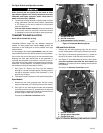
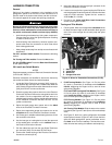
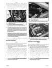
3. See Figure 16. Remove the ground screw (1), located:
• Under the seat on some 1996-2003 models, or
• Near the swingarm on 1995 or earlier models, and 1996-
2003 models without a screw under the seat.
• On the engine near the starter on 2004 and later models.
4. See Figure 27. Select the correct ring terminal (6 or 7)
from the kit to fit the ground screw.
5. Cut the black wire on the garage door opener wire harness
to easily reach the ground location, and crimp the ring
terminal to the end of the wire per the Packard crimping
tool instructions in the service manual appendix.
6. Install the ring terminal onto the ground screw threads.
Fasten the ground screw at the original location, and
secure per the torque specification in the service manual.
7. Proceed to the Orange/White Lead Connection section
for the specific model.
-J02028 8 of 16