


13
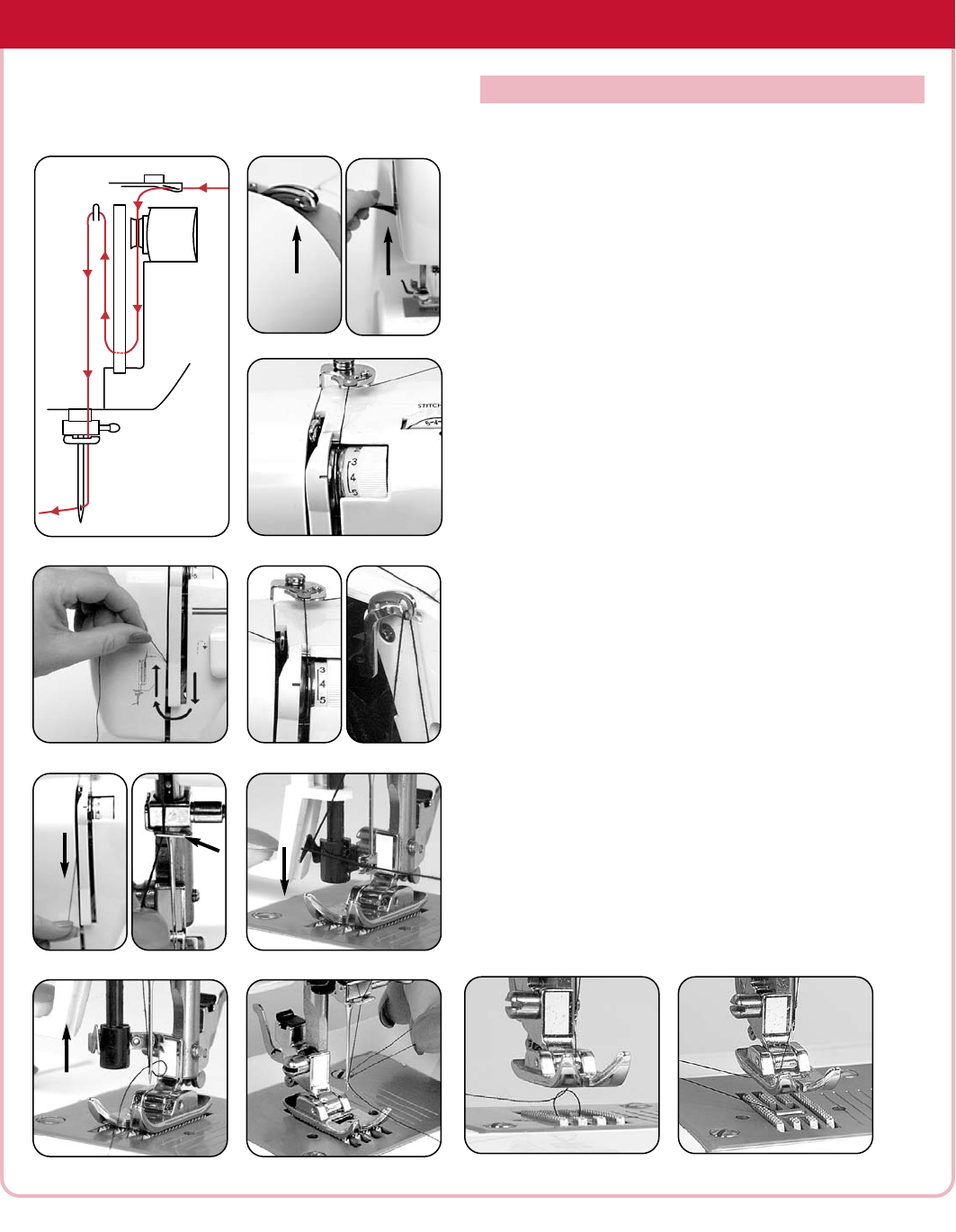
THREADING YOUR SIMPLICITY SEWING MACHINE
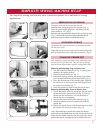
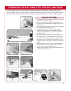
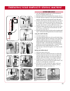
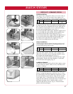
1. Turn the handwheel toward you to raise the take-up
lever to its highest position [Fig. 1].
2. Raise the presser foot to release the thread tension [Fig. 2].
3. Place felt cushion on spool pin. Place spool of thread on the
spool pin with thread coming from the back of the spool.
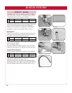
4. Snap the thread into the first thread guide at the top of
the machine and bring the thread down between the
tension discs [Fig. 3], down the right slot of the thread-
ing path, then across to and up the left slot [Fig. 4].
5. Bring the thread through the take-up lever from right
to left [Fig. 5], making sure the thread falls into the
take-up lever slot [Fig. 6].
6. Bring the thread back down the left slot of the threading path
[Fig. 7] and into the thread guide above the needle [Fig. 8].
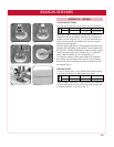
Using the needle threader
1. Lo
wer the presser foot.
2.
Lower the needle threader lever with your left index finger
and pull the thread to the left, catching it on the large hook.
Hold the needle threader lever in its lowest position and
pull the thread to the right, between the prongs that are
around the needle. A mini hook that passes through the
needle’s eye will catch the thread [Fig. 9]. Gently hold the
thread and raise the needle threader lever [Fig. 10].
3. Pull the loop of thread through the eye of the needle
[Fig. 11].
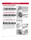
Raising the bobbin thread
1. Raise the presser foot lever.
2. Hold the end of the needle thread with your left hand.
Turn the hand wheel toward you with your right hand
until the needle goes down once and comes back up,
stopping when the needle is at its highest position.
3. Gently pull up on the needle thread [Fig. 12]. The
bobbin thread, looped around the needle thread, will
be drawn up through the needle hole.
4. Pull about six inches of both the upper and lower
threads toward the back of the machine, placing
them under the presser foot [Fig. 13].
UPPER THREADING
Fig. 3
Fig. 4
Fig. 5
Fig. 7
Fig. 1
Fig. 12
F
ig. 13
Fig. 9
Fig. 6
Fig. 8
T
hreading Diagram
Fig. 2
Fig. 10
Fig. 11