


Page 28
ProMinent
®
Dulcodes UV-Desinfektionsanlage
Technical data
230 V ± 10 % 50/60 Hz 11.7 W
115 V ± 10 % 60 Hz 11.7 W
230 V ± 10 % 50/60 Hz 6.5 W
115 V ± 10 % 60 Hz 6.5 W
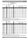
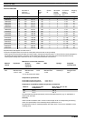
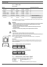
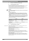
3.1.4 Motor data
Electrical Data
Motors: Identcode characteristic
3 ph IP 55 230 V/400 V 50 Hz 0.25 kW 1.62/0.94 A S
3 ph IP 55 230 V/400 V 60 Hz 0.25 kW 1.42/0.82 A S
1 ph AC 230 V 50/60 Hz 0.18 kW 1.7/1.5 A M
1 ph AC 115 V 60 Hz 0.18 kW 3.3 A N
3 ph EXe or EXde 230 V/400 V 50 Hz 0.18 kW 1.1/0.7 A L
3 ph EXe or EXde 230 V/400 V 60 Hz 0.18 kW 1.1/0.6 A P
3 ph IP 55 230 V/400 V 50/60 Hz 0.37 kW ...... R Version with external fan
1 PH 230 v; 50/60 Hz and PTC
1 ph IP 55 230 V 50/60 Hz 0.37 kW ..... V Three phase motor with integrated
speed changer, (see chapter 11)
For more details you can request the motor specification sheets. Custom motors and/or custom
motor flanges are available on request.
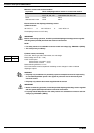
WARNING
• EX-pump only: Drive motors must be secured by an appropriate motor protection switch.
A motor protection approved for this application must be used for Ex“e”-motors.
(Protection against heating due to overload)
• EX-pump only: motors in EX-areas must be installed and checked by persons with
“recognised skills”!
• EX-pump only: observe the operating manual supplied with the EX motor!
Fuse data
IMPORTANT
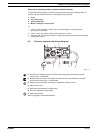
• The motors are not fuse-protected. Fit a motor circuit breaker!
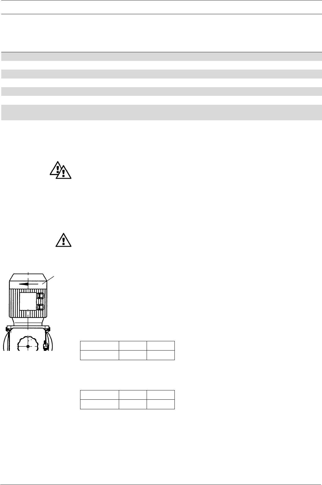
•
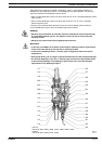
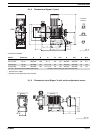
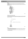
When connecting the motor, make sure that it rotates in the correct direction (see Fig. 11
).
Protection against accidental contact and moisture (IP)
Motor: IP 55 DIN EN 60034-5 (in accordance with DIN VDE 0470 Part 1, corresponds to
EN 60529 and IEC 529).
External fan
Notes on the speed-controlled motor with separate fan and temperature monitoring may be
found in the “General Operating Instructions ProMinent
®
Motor-Driven Metering Pumps and
Hydraulic Accessories”.
3.1.5 Stroke actuator drive mechanism
Cf. “Appendix” for terminal connection diagram.
3.1.6 Stroke adjuster drive mechanism
Cf. “Appendix” for terminal connection diagram.
3.1.7 Electrical data, stroke sensor “Sigma”
a) Reed contact (Identcode characteristic “Stroke sensor”: 1)
Pin 1 (white) = 4.5 V to 24 V, max. 10 mA
Pin 2 (brown) = OUT, open collector, 24 V, 20 mA
Pin 3 (green) = GND
Pulse width (low) ≥ 4 ms (depending on gearbox and power frequency)
Fig. 11
direction
of rotation