


9
INSTALLATION
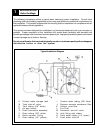
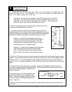
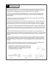
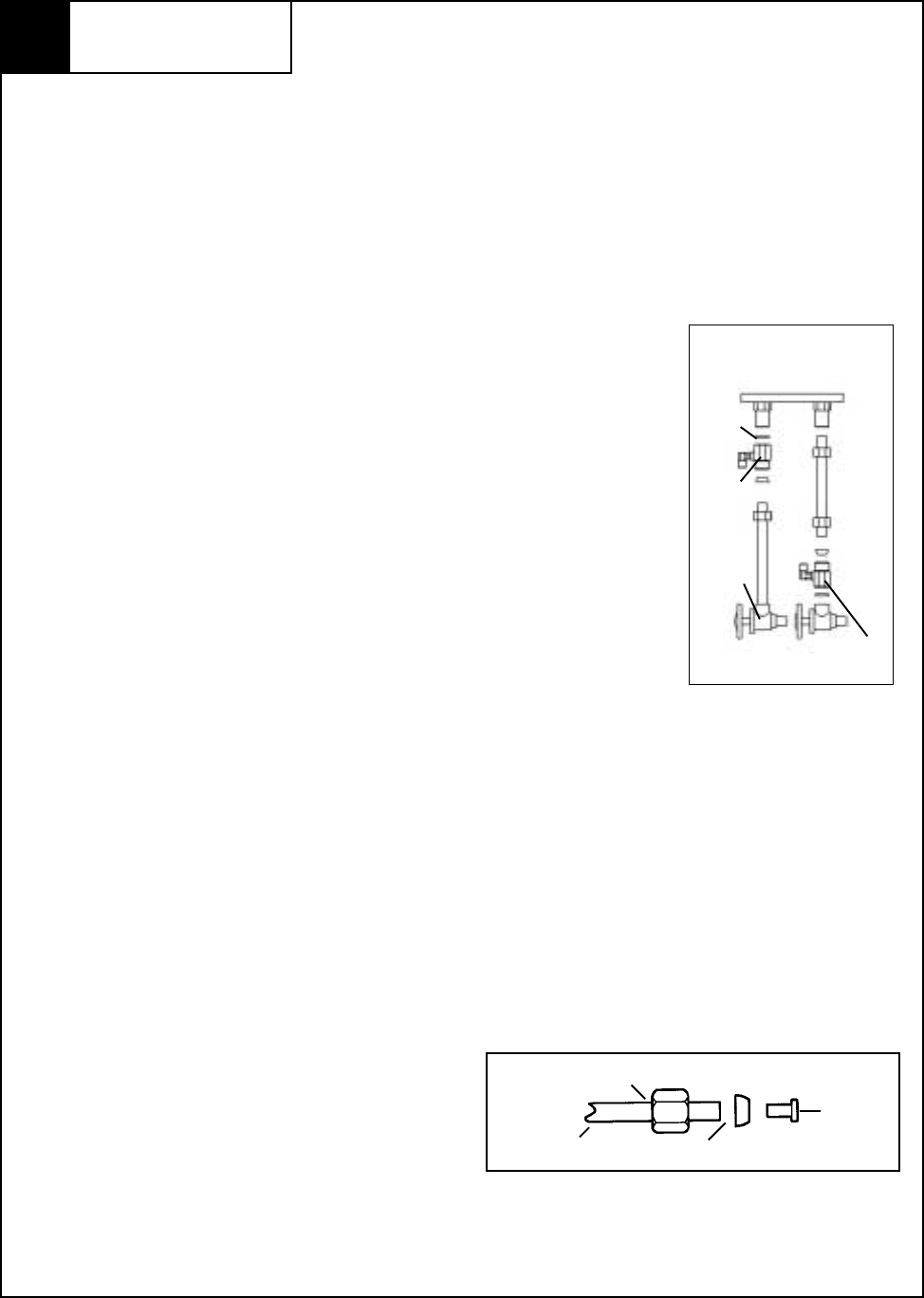
Feed Connection
Fig.1
A
B
Options
1. Locate and turn off the angle stop valve on the cold water line feeding the sink
where the Sierra unit is to be installed. This valve will usually be located under the
sink on the pipe coming out of the wall.
Hint: Be sure to make this connection on the COLD water feed, not the HOT
water feed. If you are not sure which line is the cold water line, open the hot
water tap on the sink until hot water flows from the faucet. The hot water line
under the sink can then be identified by touch.
2. When the angle stop valve is closed, relieve pressure in the line
by opening the cold water tap on the sink.
3. It may be possible to install the feed adapter fitting at either the
angle stop valve or at the faucet inlet connector depending on the size
and type of fittings at your location. The angle stop valve is preferable
because of its easier accessibility. Both options are given in Fig 1.
Option A - To install the feed adapter at the faucet
connector disconnect the cold water feed line where
it connects to the faucet inlet connector. This will
usually require an open end wrench, pliers, or long
reach faucet wrench. Proceed to step 4.
Option B - To install the feed adapter at the angle stop
valve, disconnect the feed line at the angle stop
valve. This will usually require a wrench or pliers.
With this end of the water line free, proceed to step
4.
4. Take the 1/4" feed connector valve from the parts kit and install it into the brass feed connector
adapter. Use a crescent wrench or open-end wrench to tighten the valve into the adapter (Option
B shown in Fig. 1). If the feed adapter is to be installed at the faucet inlet connector (Option A
shown in Fig. 1) it may be necessary to install the feed connector valve after step 5 due to limited
space.
5. Using the flat and cone washers as necessary, install the feed adapter into the faucet inlet
connector or angle stop valve as chosen above. Then reconnect the cold water feed line to the
open end of the feed adapter. Tighten all con-
nections securely.
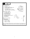
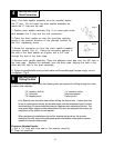
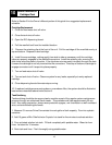
6. Using the green 1/4" tubing, install the com-
pression nut, plastic ferrule, and plastic tube
insert. Secure the tubing into the feed connec-
tor valve. Tighten the tubing retaining nut se-
curely. See Fig.2.
7. Obtain the small feed valve warning tag from the parts bag and attach it by its wire ties to the
feed valve.
3
Fig. 2
INSERT
FERRULE
COMPRESSION NUT
TUBING
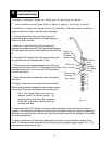
Rubber
Washer
Shut-Off
Valve
Angle
Stop
Valve
Std. Feed
Connec-
tor