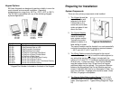
The Installation Procedure
6. Do NOT mount Keypad at this time.
7. Proceed to Install the Wiring Cable.
Required Tools
Mounting Instructions 12 Pad 3x4: KP-34S, KP-34B or KP-34K
You will need the following tools:
The 3x4 keypad is designed to mount to a single gang
switchbox or on a wall, pedestal or any flat surface of at least 3
½ by 5 ¼”. The composition of the mounting surface will
determine the fastening method required. If mounting to a
surface other than a switchbox:
• Medium sized, Phillips head
screwdriver
• 1/8” standard screwdriver
• Drill
• 7/8” or 1” (25mm) drill bit
• 1/2” (16mm) drill bit
• 5/32” (4mm) drill bit (For 12-Pad 3x4)
• 3/16” (6mm) drill bit (For 5-Pads & Thinline 2x6)
Prepare the Keypad for Installation
1. Select a flat surface (3 ½” by 5 ¼”) near the door where
you wish to install the keypad.
There are different procedures for mounting each Keypad.
Locate the Keypad part number on the back of the Keypad
and follow appropriate mounting instructions below. Keypad
templates are included with each Keypad (except KP-34’s) to
assist with the installation.
2. Drill the large hole for the Keypad connector using a 7/8”
(25mm) drill bit.
3. Place the connector on the back of the keypad in the large
hole. Mark the keypad mounting holes.
4. Drill clearance holes in accordance with fastening method
used. (If mounting to wood, drill small pilot holes and use
#6 flat head wood screws provided. If mounting to metal,
drill two 5/32" clearance holes for #6 flat head machine
screws provided.)
Mounting Instructions 5 Pad Non Illuminated: KP-5S and KP-5SL
1. Select flat mounting surface 3" X 7".
2. Use “Template A” (included with the Keypad) to mark
locations of holes A, B, and C.
3. Locate and drill the large hole marked “A”. Hole must be at
least 7/8" (22mm) diameter.
5. Do NOT mount the keypad at this time.
6. Proceed to Install the Wiring Cable.
4. Hold the Keypad against the wall with the connector
through hole “A”. Check markings for hole “B”. Re-mark if
required. If using plastic anchors, drill hole “B” using 3/16"
(6mm) bit. NOTE: Plastic anchors are provided for some
mounting applications. If anchors are not used, holes “B”
and “C” must be smaller than 3/16".
Mounting Instructions Thinline 2x6: KP-26TS, KP-26TI, KP-26TB
or KP-26TR
The Thinline 2x6 is designed for mullion mount applications. It
can also be mounted on a wall, pedestal or any flat surface of
at least 1 ¾” by 7”. The composition of the mounting surface
will determine the fastening method required:
5. Using the template, verify the hole marked “C” is aligned
and then drill hole “C”.
1. Select a flat surface (1 ¾ ” by 7”) near the door where you
wish to install the keypad.
6. Install the metal mounting bracket into hole “C” with the
screw provided.
2. Using the Thinline template, mark location of holes.
3. Drill the large hole using a 1” (25mm) drill bit.
7. Do NOT mount Keypad at this time.
4. Place the connector on the back of the keypad in the large
hole to verify that the mounting holes are aligned. Make
adjustments if necessary.
8. Proceed to Install the Wiring Cable.
Mounting Instructions 5 Pad Illuminated: KP-5DI and KP-5SI
1. Select a flat surface 1 ¾" X 7".
5. Drill mounting holes in accordance with fastening method
used. If mounting to wood, drill small pilot holes and use
#6 flat head wood screws provided. If mounting to metal,
drill two 5/32" clearance holes for #6 flat head machine
screws provided.
2. Use “Template B” (included with the Keypad) to mark holes
A, B and C.
3. Locate and drill the large hole marked “A”. Hole must be at
least 7/8" (22mm) diameter.
4. Check markings for holes “B” and “C”. Re-mark if required.
Drill holes ”B” and “C” using 3/16" (6mm) bit.
6. Do NOT mount the keypad at this time.
7. Proceed to Install the Wiring Cable.
5. Install the metal mounting bracket with the screws
provided.
6
7


