


Table of Contents
ESSEX ELECTRONICS, INC.
INTRODUCTION.......................................................................................2
KE-265 Series
OVERVIEW..............................................................................................2
All rights reserved. No part of this documentation may be
reproduced in any form, without prior written consent of Essex
Electronics, Inc. Essex Electronics shall not be liable for errors
contained in this manual. The information in this document is
subject to change without notice. Essex Electronics, Inc. reserves
the right to modify this documentation and to make improvements
or changes to the product(s) contained in this documentation at
any time.
Document Information
IOMKE265.0406.Rev D
Installation/Operations Manual for KE-265, April 2006
Revision D
This documentation is applicable to the KE-265 with Rev. C on the date code
label. (Located on the control module circuit board). This documentation is also
applicable to prior revisions except where noted.
Trademarks
Keyless Entry
®
is a registered trademark of Essex Electronics, Inc.
Lexan
®
is a registered trademark of General Electric Co., USA.
Contact Information
Essex Electronics, Incorporated
1130 Mark Avenue
Carpinteria, CA 93013
(805) 684-7601
FAX (805) 684-0232
Website: keyless.com
General email: essex@keyless.com
Technical Support email: support@keyless.com
SYSTEM SPECIFICATIONS ........................................................................2
INPUT REQUIREMENTS.............................................................................3
OUTPUT CAPABILITIES.............................................................................3
KEYPAD OPTIONS....................................................................................4
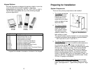
PREPARING FOR INSTALLATION.........................................................5
SYSTEM COMPONENTS............................................................................5
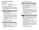
THE INSTALLATION PROCEDURE........................................................6
REQUIRED TOOLS ...................................................................................6
PREPARE THE KEYPAD FOR INSTALLATION................................................6
INSTALL THE WIRING CABLE.....................................................................8
MOUNT THE KEYPAD ...............................................................................8
PREPARE THE DOOR FOR THE ELECTRIC STRIKE ......................................8
INSTALLING THE CONTROL MODULE .........................................................8
CONNECTING THE LOCKING DEVICE .........................................................9
BATTERY BACKUP ...................................................................................9
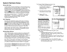
SYSTEM HARDWARE SETUP ..............................................................10
REMOTE BY-PASS.................................................................................10
ANTI-TAILGATING ..................................................................................10
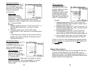
SETTING RELAY OPTIONS......................................................................10
.....................................................................13 TAMPER ALARM LOCKOUT
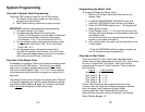
....................................................................14 SYSTEM PROGRAMMING
OVERVIEW OF SYSTEM CODE PROGRAMMING.........................................14
OVERVIEW OF THE MASTER CODE .........................................................14
PROGRAMMING THE MASTER CODE .......................................................15
OVERVIEW OF USER CODES ..................................................................15
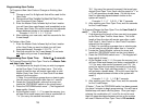
PROGRAMMING USER CODES ................................................................16
.........................................................16 PROGRAMMING DOOR OPEN TIME
............................................................................18 TROUBLESHOOTING
..................................................................20 REPAIRS AND WARRANTY
REPAIR POLICY
WARRANTY
.....................................................................................20
...........................................................................................21
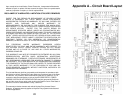
..........................................23 APPENDIX A – CIRCUIT BOARD LAYOUT
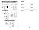
.....................................24 APPENDIX B - TYPICAL WIRING DIAGRAMS
....................................................................................................25 NOTES
Copyright © 2001-2006 Essex Electronics, Inc. All rights reserved.
1