


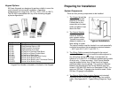
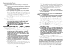
Preparing for Installation
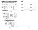
Keypad Options
All Essex Keypads are designed to perform reliably in even the
most extreme environmental conditions. Operating
temperatures can range from -40°C to +70°C (-40°F to 160°F).
The KE-265 is compatible with any of the following Keypad
styles/configurations
:
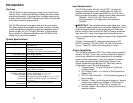
System Components
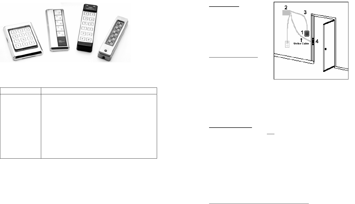
There are four primary components to be installed:
Part Number * Description
KP-5S
KP-5SL
KP-5DI
KP-5SI
KP-34S
KP-34B
KP-34K
KP-26TS
KP-26TB
KP-26TI
KP-26TR
5-Pad Stainless Steel
5-Pad Stainless Steel w/ LED
5-Pad Duranodic Illuminated
5-Pad Stainless Illuminated
12-Pad 3x4 w/ Stainless Steel Bezel
12-Pad 3x4 w/ Brass-Finished Bezel
12-Pad 3x4 w/ Black Bezel
Thinline 2x6 w/ Stainless Steel Overlay
Thinline 2x6 w/ Brass Overlay
Thinline 2x6 w/ Black Lexan
®
Illuminated Overlay
Thinline 2x6 w/ Braille Overlay
* Keypad Part Number is located on the back of the Keypad
KP-34S
KP-34B
KP-34K
KP-5S
KP-5SL
KP-26TS
KP-26TB
KP-26TI
KP-26TR
KP-5SI
KP-5DI
5
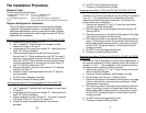
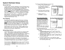
1.
The Keypad should be
mounted on the wall
adjacent to the door.
It should be on the
same side as the door
strike and about 4 feet
above the floor.
2.
The Control Module
should be mounted
inside the building
near a power source.
Typically the control
module is hidden in a
false ceiling or closet.
The control module must be located in an environmentally
controlled area where the temperature remains between
– 40°C and +49°C (-40° F and 125° F.)
Typical Installation
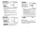
3.
The Wiring Cable connects the keypad to the control
module. It is important
not to locate the cable adjacent to
any wiring that carries line voltage. Included with the
system is a 15-foot CL2 12 conductor jacketed wiring cable
of which only 11 wires are used. If the Control Module
must be located further than 15 feet from the Keypad,
additional cable may be spliced. The maximum distance
between the Keypad and the Control Module must not
exceed 1,000 feet (250 feet for an Illuminated 5-Pad). For
runs over 200 feet, 18 gauge wire should be used. Under
200 feet, 20 gauge is acceptable.
4.
The Electric Strike/Other Locking Device(not included)
connects to the KE-265’s Main Relay output via a strike
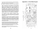
cable. (See Appendix B – Typical Wiring Diagrams. Page
24)
4