


Introduction
Input Requirements
The KE-265 accepts 12 to 24 volts AC/DC. An optional
battery charging module and rechargeable Gel Cells are
available to keep the system operational for up to 24 hours
during a power interruption. System current draw (maximum):
Overview
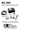
The KE-265 is an easy to program, easy to use, stand-alone
Keyless Entry
®
system with features suitable for basic access
control requirements. Providing either a voltage output or dry
contact closure, the KE-265 is designed to control any fail-safe
or fail-secure electric locking device.
Standby: 10mA at 12 volts, 25mA at 24 volts
During Operation: .25 amps max (with illuminated
Keypad)
The KE-265 features one master code and five user codes.
Two relay outputs are available to provide a variety of access
control configurations including single door operation with an
auxiliary output for a CCTV/Light Controller, a Gate/Garage
Door controller or Doorbell activation or the KE-265 can be
configured for two door operation.
⊗IMPORTANT: The maximum current draw allowed is 1 amp.
(3 amps with battery back-up for fail-secure applications only.)
Check the specifications of your locking device. Make sure
that the locking device and the KE-265 (.25 amps) combined
draw less than 1 amp. For locking devices that draw more
current, a separate power supply is required. (See Appendix B
– Page 24)
System Specifications
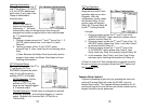
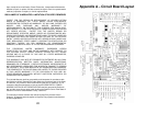
Note: If connecting DC, make the connections to “DC
IN/OUT” instead of “12-24V AC/DC IN” (see Circuit Board
Layout – Page 23). Make sure the polarity is correct.
Input Requirements: 12 to 24V AC/DC
Standby Current Draw: 12V Î 10 mA
24V Î 25 mA
Outputs: 2 SPDT Relay contacts at 6 amps (120VAC)
Voltage or Dry Contact
Fail Safe or Fail Secure Relay Configuration
Programmable Output:
(Door Open Time)
1 to 120 seconds
Default Î 5 seconds
Latching: Manual (Toggle On/Off)
# of User Codes: 6 Codes (1 Master, 5 User)
Code Length: 3 to 8 Digits
Default Master Code: 1-3-5-7-9
Tamper Alarm: 25 Incorrect Key Presses
Access Code Protection: Non-Volatile Memory
Keypad Operating
Environment:
- 40° C to + 70° C (- 40° F to + 160° F)
100 % Relative Humidity
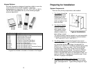
Keypad Dimensions:
5 Pad Non Illuminated
5 Pad Illuminated
12-Pad 3x4
Thinline 2x6
KP-5S, KP-5SL Î 6 ⅝” x 2 ¼” x ½”
KP-5DI, KP-5SI Î 6 ½” x 1½” x ⅞”
KP-34S, KP-34K, KP-34B Î 5 ⅛” x 3 ⅜” x 7/16”
KP-26TS, KP-26TB, KP-26TI, KP-26TR Î 7 ⅛”
x 1 ¾” x ¾”
Control Module Operating
Environment:
- 40° C to + 49° C (- 40° C to + 120 ° F)
Control Module Dimensions: 7½“ x 5½“ x 2½“
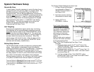
Output Capabilities
The KE-265 provides two SPDT dry contact relays (rated at 6
amps at 120 VAC). Each relay can be configured to perform
one of many different functions depending on the specific
access control requirement. User Authorization to control
each relay is determined by Setting Relay Options (see
System Hardware Setup Î page 10). Each relay can be
configured for one of the following options:
1. Voltage Output – For any Fail Safe or Fail Secure
Locking Device
2. Dry Contact Output – For control of Gate Operator or
Garage Door
3. CCTV or Light Controller – First key press triggers a 10
second output
4. Doorbell – Press ∗ at the Keypad to trigger a 1 second
output for a doorbell (not included). This function is
only available with a 12 Pad 3x4 or Thinline 2x6.
5. Auxiliary Output – Momentary or Manual Control
of an
electronic device.
2
3