


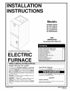

_ Installation Instructions Electric Furnace I
Electrical Wiring
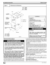
Electrical shock hazard.
Turn OFF electric power at fuse box or service
panel before making any electrical connections
and ensure a proper ground connection is made
before connecting line voltage.
Failure to do so can result in property damage,
personal injury and/or death.
All electrical work MUST conform with the requirements of local
codes and ordinances and the National Electrical Code NFPA 70
current edition.
Electrical Heaters & Operating Controls
Timelow voltage transformer and the fan control are standard on
a!l models and are prewired at the factory. To operate the blower
coil, a heater accessory or a no-heat kit must be installed. Line
voltage connections are made to the heater accessory or the no-
heat kit.
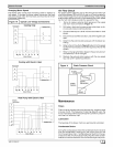
Low Voltage Control Connections
The 24 volt power supply is provided by an internally wired low
voltage transformer which is standard on all models. If power
supply is 208 volt, the low voltage transformer must be rewired to
the 208 volt tap. See the unit wiring label.
Field supplied low voltage wiring can enter the unit on the top left
hand corner or the left hand side panel. When using the left hand
side panel entrance, the low voltage wiring must be fed through
the entrance hole in the bottom of the control box.
Install the strain relief bushing (supplied with unit) in the selected
hole and a hole plug (supplied with unit) in the unused hole.
Connect the field wiring at the screw terminals of the control
board. Refer to Figure 9.
Keep the low voltage wiring as short as possible inside the control
box.
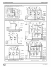
Complete connections between indoor blower, outdoor section,
indoor thermostat and electronic outdoor thermostat (accessory)
according to instruction provided with the Condenser Installation
Instructions or those provided with the accessory and refer to Fig-
ure 10.
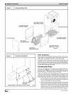
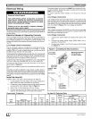
Install No Heat Kit
If electric heat is not used, install accessory No Heat Kit.
1.. Locate adapter and filler plates, with screws inside pack-
age unless they were preinstalled at the factory.
2.. If necessary, attach adapter plate and filler plate to bracket
as required to match cabinet, Refer to Figure 9.
3.. Secure the no heat accessory with four screws.
4.. Connect the plug from No Heat Kit wiring into the recep-
tacle on the control board on the side of the cabinet.
Overcurrent Protection
The power supply wiring to the unit MUST be provided with over-
current protection. Governing codes may require this to be fuses
ONLY or circuit breakers.
For blower cabinets without heaters, a 15 amp circuit may be
used.
Line Voltage Connections
Line voltage wiring may be brought into the unit through the top
right-hand corner or the right-hand side panel. The correct hole
size required by the conduit fitting must be punched at the pilot
hole location. Plug the unused pilot hole with a hole plug (supplied
with unit). Refer to Figure 9 for line voltage connections.
Grounding
Use a copper conductor (#14AWG) from the unit to a grounded
connection in the electric service panel or a properly driven and
electrically grounded ground rod.
Line Voltage Connection
1. A disconnect switch MUST be located within sight of the
unit.
2. Provide line voltage power supply (208V-240V) from a
separate 15 amp circuit.
3. Connect line voltage L1 and L2 to the lugs on the No Heat
Kit, Figure 9.
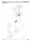
Figure 9 Installing No Heat Accessory
Low Voltage / Matching Receptable
Connections /_;_Z] / For No Heat Kit
_,_ ____/._ or Electric Heater
Adapter Plate _ 0_"--.._ _
No Heat Kit. '_: _,_ __/
Lugsfor
LineVoltage
and Ground
Connections
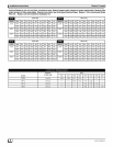
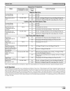
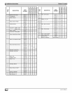
No Heat
Model
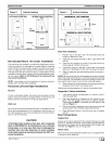
AMF00tNH
SupplyCircuit
Volts Phase He_z
240 1 60
208 1 60
Supply
Circuit
No.
Single
Single
Maximum
Motor
AMPS.
6.0
6.0
Total
AMPS.
6.0
6.0
No Heat Kit Technical Data
Branch
Circuit
Ampacity
7.5
7.5
Maximum
Overcurrent
Protective
Device
(AMPS.) No.
15 2
15 2
Recommended
SupplyWire
750 C. Copper
Max,
Size Length (Ft)
14 104
14 90
Ground
Wire
No. Size
1 14
1 14
L_J 442 01 2204 01