


JElectric Furnace Installation Instructions j
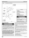
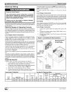
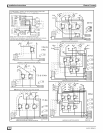
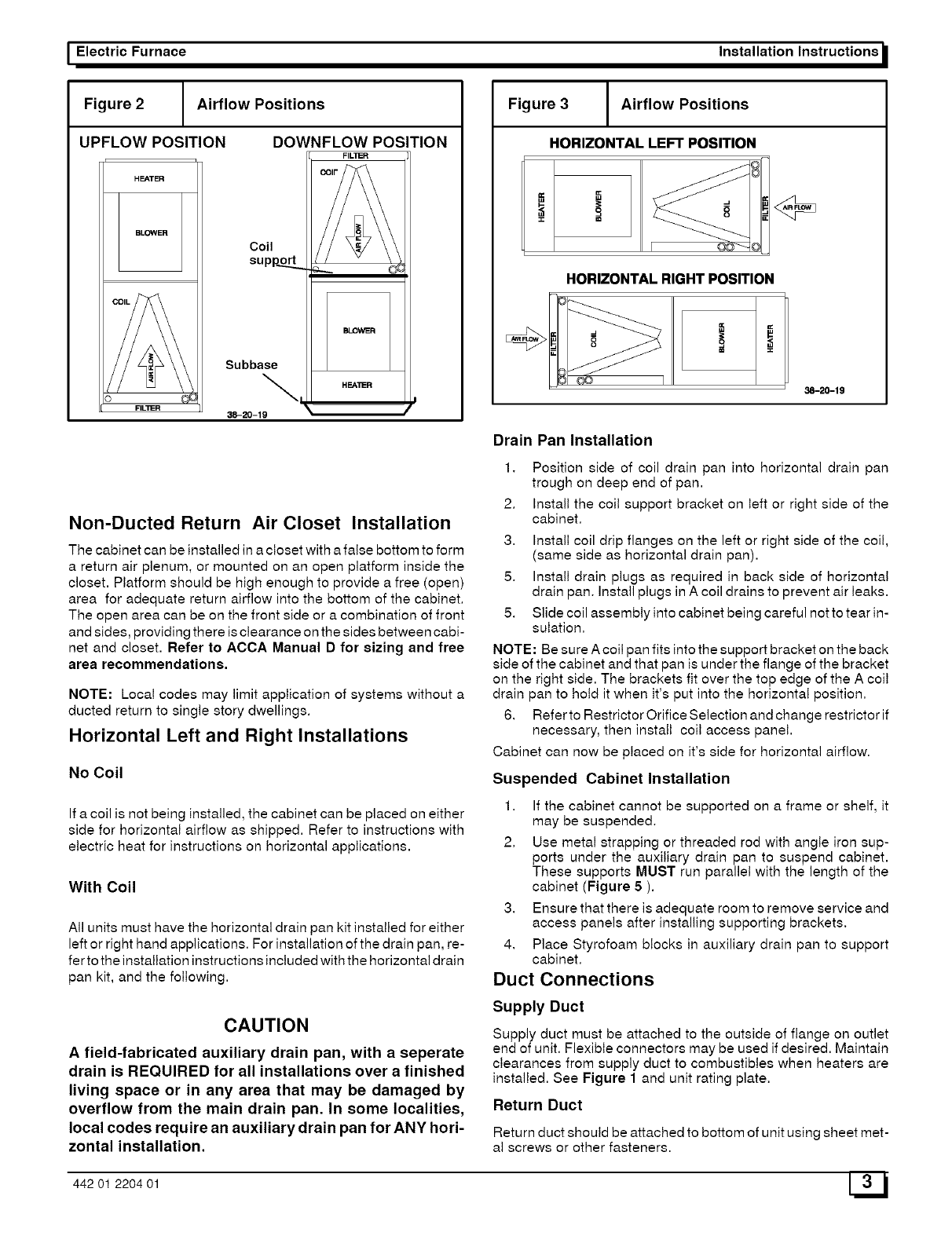
Figure 2 Airflow Positions
UPFLOW POSITION
HEATER
BLOWER
FIL_ER
DOWNFLOW POSITION
FILLER
Coil
supop.._
Subbase
\,
38-20-19
HEA'_R
\ /
Non-Ducted Return Air Closet Installation
The cabinet can be installed in a closet with a false bottom to form
a return air plenum, or mounted on an open platform inside the
closet. Platform should be high enough to provide a free (open)
area for adequate return airflow into the bottom of the cabinet.
The open area can be on the front side or a combination of front
and sides, providing there isclearance on the sides between cabi-
net and closet. Refer to ACCA Manual D for sizing and free
area recommendations.
NOTE: Local codes may limit application of systems without a
ducted return to single story dwellings.
Horizontal Left and Right Installations
No Coil
Ifa coil is not being installed, the cabinet can be placed on either
side for horizontal airflow as shipped. Refer to instructions with
electric heat for instructions on horizontal applications.
With Coil
All units must have the horizontal drain pan kit insta!led for either
left or right hand applications. For installation ofthe drain pan, re-
fer tothe installation instructions included with the horizontal drain
pan kit, and the following.
CAUTION
A field-fabricated auxiliary drain pan, with a seperate
drain is REQUIRED for all installations over a finished
living space or in any area that may be damaged by
overflow from the main drain pan. In some localities,
local codes require an auxiliary drain pan for ANY hori-
zontal installation.
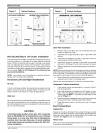
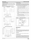
Figure 3 Airflow Positions
HORIZONTAL LEFT POSITION
,,=,
m
HORIZONTAL RIGHT POSITION
38-20-19
Drain Pan Installation
1,
2.
3.
5.
5.
Position side of coil drain pan into horizontal drain pan
trough on deep end of pan.
Install the coil support bracket on left or right side of the
cabinet.
Install coil drip flanges on the left or right side of the coil,
(same side as horizontal drain pan).
Install drain plugs as required in back side of horizontal
drain pan. Install plugs in A coil drains to prevent air leaks.
Slide coil assembly into cabinet being careful not to tear in-
sulation.
NOTE: Be sure A coil pan fits into the support bracket on the back
side of the cabinet and that pan is under the flange of the bracket
on the right side. The brackets fit over the top edge of the A coil
drain pan to hold it when it's put into the horizontal position.
6. Referto Restrictor Orifice Selection and change restrictor if
necessary, then install coil access panel.
Cabinet can now be placed on it's side for horizontal airflow.
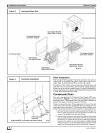
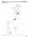
Suspended Cabinet Installation
1. If the cabinet cannot be supported on a frame or shelf, it
may be suspended.
2. Use metal strapping or threaded rod with angle iron sup-
ports under the auxiliary drain pan to suspend cabinet.
These supports MUST run parallel with the length of the
cabinet (Figure 5 ).
3. Ensure that there is adequate room to remove service and
access panels after installing supporting brackets.
4. Place Styrofoam blocks in auxiliary drain pan to support
cabinet.
Duct Connections
Supply Duct
Supply duct must be attached to the outside of flange on outlet
end of unit. Flexible connectors may be used if desired. Maintain
clearances from supply duct to combustibles when heaters are
installed. See Figure 1 and unit rating plate.
Return Duct
Return duct should be attached to bottom of unit using sheet met-
al screws or other fasteners.
442 01 2204 01 3[._J