


_ Installation Instructions Electric Furnace]
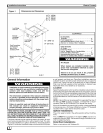
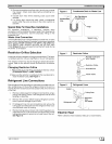
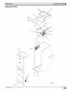
Figure 1 Dimensions and Clearances
14-3/8 '' (EF08)
17-7/8 '' (EF12)
21-1/2" (EF16)
25-1/8" (EF20)
LowVoltage
PilotHole
Alternate
LineVoltage
Pilot Hole
DrainConnections
For Horizontal
Main3/4Fpt
Overflow 3/4 FPT
Main/OverflowDrains
3/4FPT
W
16-3/8'' (EF08)
19-7/e'' (EF12)
23-1/2'' (EF16)
27-1/e'' (EF20)
LineVoltage
Pilot Hole
Suction-
Liquid
FilterDoor
45" (EF08-12)
54" (EF16-20)
21 1/2"
38-20-17
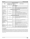
CLEARANCES
NO HEATERS
All Sides .................................. O"
From Supply Duct .......................... O"
Recommended Service From Front .......... 20"
(Service for blower, filter if installed)
WITH HEATERS
All Sides .................................. O"
From First Three
Feet of Supply Duct to Combustibles ........ 1"
From Duct after Three Feet ................. O"
Recommended Service From Front .......... 20"
(Service for blower, filter, heaters if installed)
Fire Hazard
When heaters are installed maintain clear-
ances from combustible materials as speci-
fied on unit rating plate.
Failure to do so can result in fire, property
damage, personal injury or death.
General Information
Installation or repairs made by unqualified persons can
result in hazards to you and others. Installation MUST
conform with local building codes and with the
National Electrical Code NFPA70 current edition.
The information contained in this manual is intended
for use by a qualified service technician familiar with
safety procedures and equipped with the proper tools
and test instruments.
Failure to carefully read and follow all instructions in
this manual can result in equipment malfunction,
property damage, personal injury and/or death.
THESE INSTRUCTIONS ASSUME THAT A TYPICAL INSTAL-
LATION WILL INCLUDE ELECTRIC HEAT AND A COIL. BA-
SIC INSTRUCTIONS ARE PROVIDED BUT THE INSTALLER
WILL HAVE TO REFER TO INSTRUCTIONS FOR OTHER AC-
CESSORIES FOR MORE COMPLETE INFORMATION.
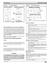
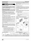
The blower cabinet may be used as an electric furnace or forcool-
ing or heat pump operation with or without electric heat. The cabi-
net can be installed in an upfiow, downflow or horizontal position
(Figure 2). Horizontal installations require a horizontal kit for prop-
er coil support and drain pan. Downflow installations require a
subbase kit which provides proper clearances and a support to
install a coil.These units are not shipped with air filters installed.
Filter must be field supplied, either washable or disposal type.
Washable filters are available as an accessory.
Location
Select the best position wi_ich suits timeinstallation site conditions.
The location should provide adequate structural support, space in
the front ofthe unit for service access, clearance for return air and
supply duct connections, space for refrigerant piping connections
and condensate drain line connections, and clearance forfilter re-
moval.
NOTE: Internal filter can be accessed from separate filter door. If
the filter can NOT be easily accessed, a remote filter is recom-
mended. Refer to ACCA Manual D for remote filter sizing.
Ifthe unit islocated in an area of high humidity, nuisance sweating
of casing may occur. On these installations a wrap of 2" fiberglass
insulation with a vapor barrier should be used.
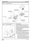
Upflow Installations
The unit is ready to install in the upflow position without modifica-
tions.
The unit MUST be supported on the bottom ONLY and set on a
supporting frame or shelf. Use screws through the bottom to an-
chor to supporting frame.
Downflow Installations
Refer to instructions with Subbase Kit.
_J 442 01 2204 01