


I Electric Furnace
3. Routetotheoutsideortoafloordrain, laundrytrayorwaste
line (sewer). Check local codes before connecting to a
sewer line.
4. Insulate drain lines where sweating could cause water
damage.
5. If a gravity drain cannot be used, install a condensate
pump. Install the pump as close to the indoor section as
possible.
SpecialNote For DownflowInstallations
For downflow installations, a secondary overflow drain
connection must be installed to prevent water from dripping onto
live electrical components. Use the secondary fitting on the
evaporator coil.
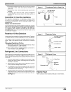
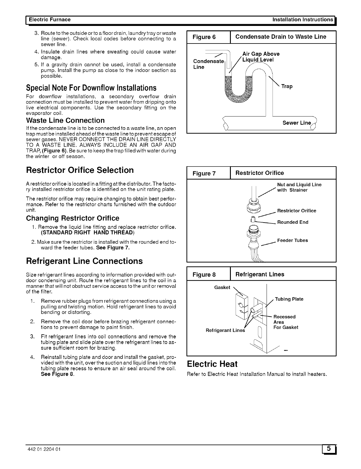
Waste Line Connection
Ifthe condensate line is to be connected to a waste line, an open
trap must be installed ahead ofthe waste line to prevent escape of
sewer gases. NEVER CONNECT THE DRAIN LINE DIRECTLY
TO A WASTE LINE. ALWAYS INCLUDE AN AIR GAP AND
TRAP, (Figure 6). Be sure to keep the trap filled with water during
the winter or off season.
Restrictor Orifice Selection
A restrictor orifice is located ina fitting at the distributor. The facto-
ry installed restrictor orifice is identified on the unit rating plate.
The restrictor orifice may require changing to obtain best perfor-
mance. Refer to the restrictor charts furnished with the outdoor
unit.
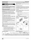
Changing Restrictor Orifice
1. Remove the liquid line fitting and replace restrictor orifice.
(STANDARD RIGHT HAND THREAD)
2. Make sure the restrictor is installed with the rounded end to-
ward the feeder tubes. See Figure 7.
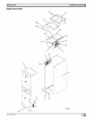
Refrigerant Line Connections
Size refrigerant lines according to information provided with out-
door condensing unit. Route the refrigerant lines to the coil in a
manner that will not obstruct service access to the unit or removal
of the filter.
2,
3.
Remove rubber plugs from refrigerant connections using a
pulling and twisting motion. Hold refrigerant lines to avoid
bending or distorting.
Remove the coil door before brazing refrigerant connec-
tions to prevent damage to paint finish.
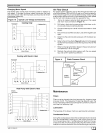
Fit refrigerant lines into coil connections and remove the
tubing plate and slide plate over the refrigerant lines to as-
sure sufficient room for brazing.
Reinstall tubing plate and door and install the gasket, pro-
vided with the unit, over the suction and liquid lines into the
tubing plate recess to ensure an air seal around the coil.
See Figure 8.
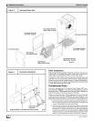
Figure 6
T
Condensate
Line
1
Installation Instructions
Condensate Drain to Waste Line
Air Gap Above
uid Level
Sewer Line_q_
Figure 7 J Restrictor Orifice
Nut and Liquid Line
_ Rounded End
_ Feeder Tubes
Figure 8 J Refrigerant Lines
Gasket ,_
Refrigerant k_ne_s__ "
-%
j Tubing Plate
Recessed
Area
For Gasket
Electric Heat
Refer to Electric Heat Installation Manual to install heaters.
442 01 2204 01 5L_ J