


SECTION 5 SERVICE TECH INFORMATION
5A. TROUBLESHOOTING
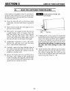
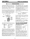
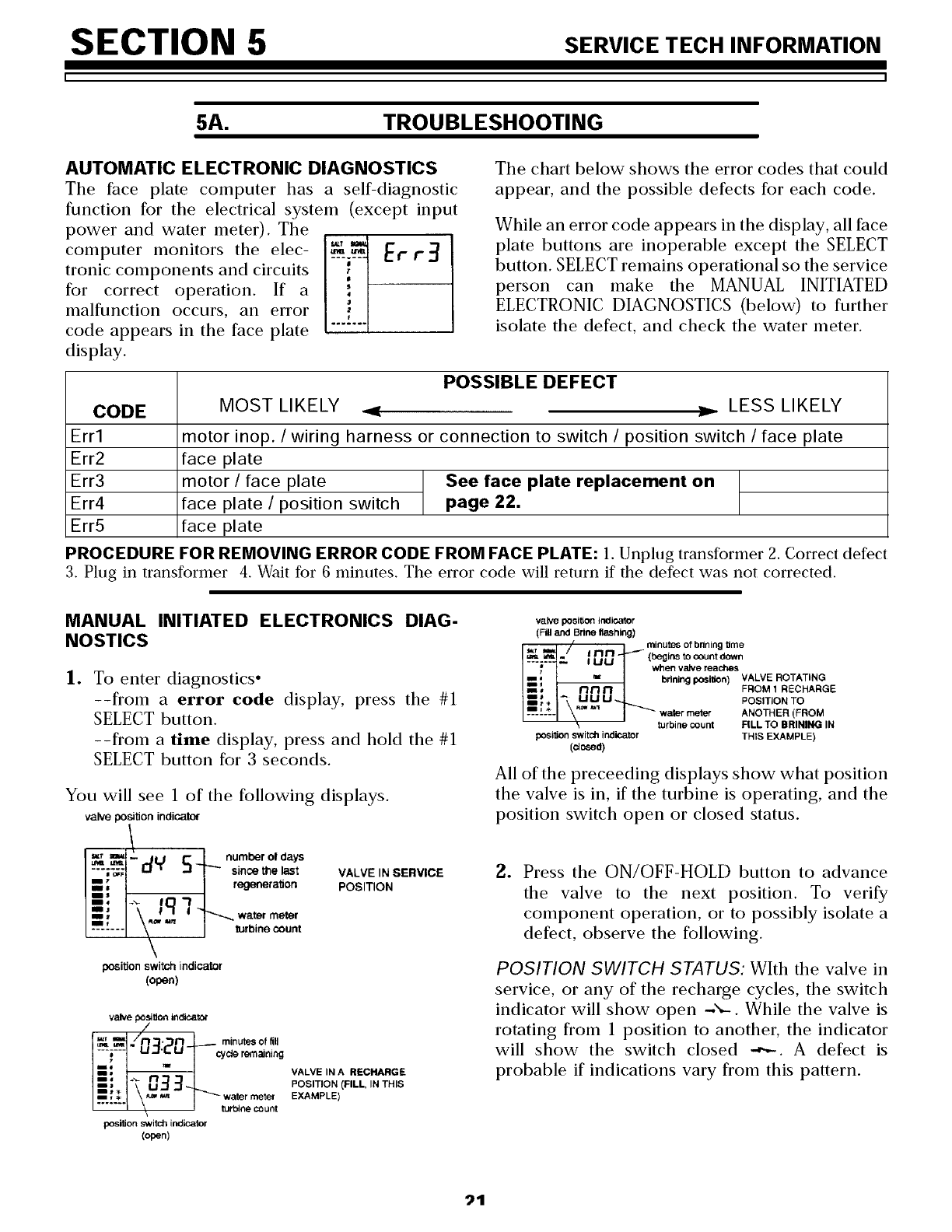
AUTOMATIC ELECTRONIC DIAGNOSTICS
The face plate computer has a self-diagnostic
function for the electrical system (except input
power and water meter). The
computer monitors the elec- _--_-- Er r_
tronic components and circuits !
for correct operation. If a
malfunction occurs, an error
f
code appears in the face plate .......
display.
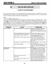
The chart below shows the error codes that could
appear, and the possible defects for each code.
While an error code appears in the display, all face
plate buttons are inoperable except the SELECT
button. SELECT remains operational so the service
person can make the MANUAL INITIATED
ELECTRONIC DIAGNOSTICS (below) to further
isolate the defect, and check the water meter.
CODE
Err1
Err2
Err3
Err4
Err5
POSSIBLE DEFECT
MOST LIKELY -_' _, LESS LIKELY
motor inop. / wiring harness or connection to switch / position switch / face plate
face plate
motor / face plate See face plate replacement on
face plate / position switch page 22.
face plate
PROCEDURE FOR REMOVING ERROR CODE FROM FACE PLATE: 1. Unplug transformer 2. Correct defect
3. Plug in transformer 4. Wait for 6 minutes. The error code will return if the defect was not corrected.
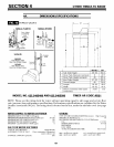
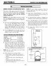
MANUAL INITIATED ELECTRONICS DIAG-
NOSTICS
lo
To enter diagnostics °
--from a error code display, press the #1
SELECT button.
--from a time display, press and hold the #1
SELECT button for 3 seconds.
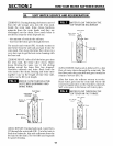
You will see 1 of the following displays.
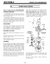
valve position indicator
_r mLi _ numberol days
il-V =_1_ " regenera*_on
_ water meter
....... turbine count
\
_ition switch indicator
(open)
VALVE IN SERVICE
POSITION
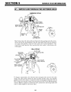
valve poytion indicator
_,_ _./n_._n 1_ rninutesoffill
I ---i:---I LI=I'L U -_ cycleremaining
I VALVE IN A RECHARGE
m _ POSITION (FILL, IN THIS
BBIt
==, * water mete{ EXAMPLE)
turt_ne count
position switch indicator
(open)
valvepositionimdicator
(Fdland Brine flashing)
• minutesofbnningbme
u_.. / iI-lrl- _-(begirmtocountdown
I UU when valve reaches
ii "_ brJrtirl_ po_i_on) VALVE ROTATING_, UU U_ POSITION TO
.... _- _--" _'_'_ wa_r meter ANOTHER(FROM
turbinecount FILLTO BRINING IN
posilionswitchindicator THIS EXAMPLE)
(dosed)
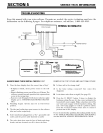
All of the preceeding displays show what position
the valve is in, if the turbine is operating, and the
position switch open or closed status.
o Press the ON/OFF-HOLD button to advance
the valve to the next position. To verify
component operation, or to possibly isolate a
defect, observe the following.
POSITION SWITCH STATUS: With the valve in
service, or any of the recharge cycles, the switch
indicator will show open -'_-. While the valve is
rotating from 1 position to another, the indicator
will show the switch closed -_-. A defect is
probable if indications vary from this pattern.