


MAINTENANCE
NOTICE: DO not overtighten; you may twist studs off of
tank. If you have a torque wrench, tighten to 85 inch-
pounds torque.
18. Stand tank on feet and reconnect piping.
19. Recharge tank to proper air pressure (see Page 5).
20. Reconnect hoses and pressure switch tube; prime pump
(see Page 6).
Air Valve Replacement
1. Follow steps 1 through 5 under _Vinyl Bag Removal",
Page 7.
2. Cut valve off as close to tank as possible. Push remaining
portion back into tank.
3. Tip tank on end and BE SURE all water is drained from
bag.
4. Carefully remove bag ring from lip on tank opening and
push bag ring back into tank; reach in around it and re-
move cut off portion of valve from tank.
5. Wipe a thin film of soapy solution on replacement valve
and from inside tank insert in hole in top of tank.
6. Pull valve through hole with pliers or a valve tool (avail-
able at your local filling station or Automotive Center).
7. Follow steps 14 through 20 under "Vinyl Bag Removal",
Page 7, to reinstall bag in tank.
Testing for Bag Leakage
1. Follow steps 1 through 4 under "Vinyl Bag Removal",
Page 7.
2. Tip tank on end, vane down. Be careful not to break
valve!
3. If bag leaks, water will run out of valve. If so, replace bag
as instructed above.
DISASSEMBLY AND
ASSEMBLY OF PUMP
I_.WARNING JRtsk of electric shock. Ground unit and
I
disconnect power before attempting any work on
pomp or motor.
Your Sears pump is designed for ease in servicing. Should
repair or replacement of the motor or seal be needed, the
pump and piping do not need to be disconnected or dis-
tuthed.
1. Disassemble pump as follows:
A. Disconnect power.
B. Drain pump by opening drain cock. Remove pressure
switch tubing from fitting on top of pump.
_WARNING]To avoid serious injory,release all
pressure fi'om system before attempting to remove
clamp from pump.
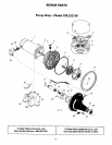
C. Remove clamp, Key No. 10, Page 12.
D. Remove pump base motmting bolts. Motor assembly
and back half assembly of pump can he pulled away
from front half.
E. Remove "O" rings.
2. Reassembly of pump.
A. Clean =O" rings and "O" ring grooves.
B. Lubricate =O" rings with petroleum jelly, and place in
grooves.
C. Slide pump halves together.
D. Clean inside of clamp. Place clamp around pump
halves. Alternately tighten clamp screw and tap clamp
around outside with plastic mallet. This will insure
proper seating of "O" ring and clamp.
E. Assemble base mounting bolts. Connect pressure
switch tubing and close drain cock.
F. Prime pump and turn on power.
G. Check for leaks.
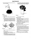
Removing Motor for Service
and Replacing Shaft Seal
If it is he4:_essary to separate motor and seal plate, always re-
place the shaft seal. We suggest you purchase this item,
UlO94SA, and have it on hand for future use.
NOTICE: The seal consists of two parts, a rotating member
and a ceramic seat. The surfaces of the seal are easily dam-
aged. Read instructions carefully.
1. Disassemble pump per instructions above.
2. Remove diffuser and impeller as follows (Key Nos. 8 and
9, Page 12).
A. Remove screws holding diffuser.
B. Loosen two screws and remove motor canopy from
motor.
C. Place 7/16" open end wrench on motor shaft flat.
D. Turn impeller counterclockwise when facing it.
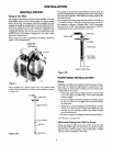
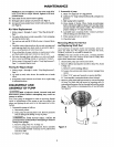
3. Remove pump back half from motor by unscrewing four
(4) nuts. Pry back half off motor by inserting two (2)
screwdrivers between the back pump half and the motor
flange. This will force rotating portion of seal off shaft.
See Figure 5.
Figure 5
4750194
8