


INSTALLATION
1-1/4" 1-1/2" 2"
Up to 25 Ft. 25 to 50 Ft. 50 to 200 Ft.
Discharge Pipe Sizes
When the pump is some distance from the house or point
of water use, the discharge pipe size should be increased to
reduce pressure losses caused by friction.
1" 1-114" 1-1/2"
Up to 25 Ft. 25 to 100 Ft. 100 to 800 Ft.
Tank
Tanks are pre-charged with 40 PSI air pressure at the factory.
Your tank requires an air ch.arge of 40 pounds per square
inch (PSI) for proper operation; check tank pressure with
tire gauge to determine flair charge needs adjustment. Tank
pre-charge should be checked annually; see instructions at
right.
In areas where the temperature is high for long periods of
time, the tank pre-charge pressure may increase. This may
reduce the tank drawdown (amount of water available per
cycle). If this occurs, reduce the pre-charge pressure to two
PSI below the pump cut-in setting of the pressure switch
(normally to 38 PSI).
It is necessary to flush all air out of the piping system and
water reservoir portion of the pre-charged tank. This is re-
quired on new installations, pumps requiring repriming and
pumps that have been disassembled for service. Do this as
fonows:
1. Open faucets furthest from tank and allow pump to op-
erate.
2. Air in the system will cause a sputtering flow; allow
faucets to run until you have a steady, air free stream.
3. Open and close faucets repeatedly until you are sure all
air has been removed.
4. If stream does not become steady, air may be leaking into
the system; check for leaks in the piping on the suction
side of the pump.
NOTICE: To prevent waterlogging, check tank air charge
annually.
To Check Tank Air Charge
If drawdown (amount of water available per cycle), de-
creases significantly, check as follows:
1. To check air charge in tank, shut off electric power to
pump, open faucet near tank, and drain completely.
2. At the air valve in top of tank, check air pressure with
standard tire gauge. Air pressure should be the same as
pump pressure switch cut-in setting (40 PSI).
3. If the air pressure is below 40 PSI, add air to the tank.
Use an air compressor or a portable air storage tank.
4. Use soap or liquid detergent to check for air leaks around
air valve. Continuous bubbling indicates a leak. If neces-
sary, install new core in air valve. This is the same as
those used for automobile tubeless tires.
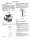
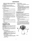
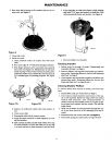
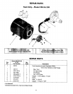
1 2
1. Tank nearly empty - air expands filling area above
vinyl separator.
2. Water begins to enter tank - air is compressed above
separator as it fills with water.
3. Pump-up cycle completed - air now compressed to
3 4 5
cut off setting of pressure switch.
4. Water being drawn from tank - compressed tank air
forces water out of separator.
5. Separator completely empty - new cycle ready to
begin.
Figure 3
Motor
Horsepower
1/2
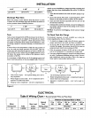
ELECTRICAL
Table II Wiring Chart - Recommended Wire and Fuse Sizes
Volts
115/230
Max. Load
Amps.
8.8/4.4
Branch
Fuse*
Rating Amps
1_15
Distance in FeetfromMotorto Meter
0'to 101'to 201'to 301'to 401'to
100' 200' 300' 400' 500'
Wire Size
14/14 12/14 10/14 8/14 8/12