


SAFETY INSTRUCTIONS (Continued)
6. Disconnect electrical power source before installing or
working on pump.
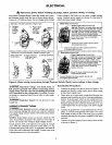
7. Ground pump with a ground wire run from grounding
lug on motor to a grounded lead in the service panel.
8. Line voltage and frequency of electrical power supply
must agree with motor nameplate.
9. Use of fuses or wire smaller than size recommended in
owner's manual can cause overheating, possible fires,
and will void warranty.
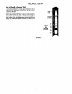
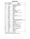
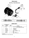
Pump
Model
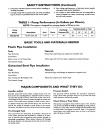
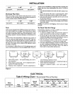
TABLE I - Pump Performance (In Gallons per Minute)
NOTE: This system is designed for pumping depths of 20 feet or less.
Description Suct. Disch.
390.252158 112HP S.W. Jet 1-1/4" 1" 40
Discharge Pumping Depth in Feet
Pressure PSI 5' 10' 15' 20'
8.2 7.3 6.2 5.0
BASIC TOOLS AND MATERIALS NEEDED
Plastic Pipe Installation
Tools
Pipe Wrenches
Screwdriver
Knife or Saw to Cut Plastic Pipe
Tire Pressure Gauge
Materials
Plastic Pipe and Fittings (as required to complete job).
Teflon Tape (DO NOT use joint compound on plastic fittings).
Galvanized Steel Pipe Installation
Materials
Galvanized Pipe and Fittings (as required to complete job).
Pipe Joint Compound or Teflon Tape
Tools
Pipe Wrenches
Screwdriver
Pipe Cutting and Threading Tools
Tire Pressure Gauge
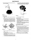
MAJOR COMPONENTS AND WHAT THEY DO
Impeller and Jet
Impeller turns with motor shaft, causing water to fly out
from its rim by centrifugal force. Impeller rotation creates a
vacuum which pulls in more water. Part of the water is di-
verted back to the jet where it passes through the nozzle and
venturi. This creates more vacuum to draw in more water.
In shallow wells (less than 20 feet deep), the vacuum cre-
ated at the pump is_enough to pull water to toe pump.
Therefore, for shallow _-ell use the jet is built into the pump.
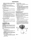
Pre-Charged Tank
The tank serves two functions, it provides a reservoir of
water under pressure and maintains a cushion of air pres-
sure to prevent pipe hammering and possible damage to
plumbing components. When water is drawn off through
the house fixtures, the pressure in the tank is lowered and
the pump starts.
Pressure Switch
The pressure switch provides for automatic operation.
Pump starts when pressnre drops to 40 pounds and stops
when pressure reaches 60 pounds.
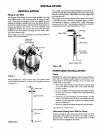
Check Valve or Foot Valve
This pump is equipped with a built-in check valve. Install a
check valve as close to well as possible o_ well point in-
stallations. A foot valve must be installed in the well on dug
or cased wells. See Figures ZA and 2B, Page 4. For long hor-
izontal pipe runs, install check valve as close to well as pos-
sible (all types of wells).
3