ELECTRICAL
SWITCH
INDICATOR LIGHT
GROUND
IN-LINE FUSE
IGNITION
IGNITION
SWITCH
STARTER
BATTERY
Figure 9
Figure 3
WHILE MAKING ELECTRICAL CONNECTION CAN RESULT IN INJURY FROM FIRE
OR ELECTRICAL BURNS.
The indicator light is rated for 12 VDC (contact factory for other voltages). Wire in accor-
dance with the American Boating and Yacht Council standard E-9 “Direct current Electri-
cal System on Boats, copies of which may be obtained from ABYC, Edgewater, MD,
USA 21037, 410-956-1050.
Supplies, which are not included with your Sea-Fire system, should be at hand before
indicator light installation, are as follows:
1. Five (5) ampere in-line fuse and holder
2. Sufficient length of insulated 16 AWG stranded wire
3. Crimp on wire connectors
4. Crimp pliers, hand tools
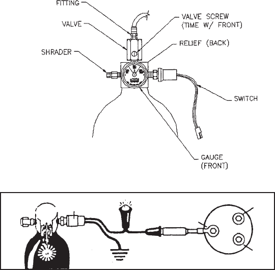
Attach one wire lead from the in-line fuse to the ignition position on the starter switch.
Connect other lead from the in-line fuse to the indicator light. Connect remaining indica-
tor lead to one of the Sea-Fire cylinder pressure switch connector wires. Connect the
remaining cylinder pressure switch lead to common ground, which may be the negative
battery buss at the control panel, or directly to the engine block (see Figure 3).
CAUTION: Electrical systems vary from vessel to vessel and these directions may not
be applicable for your installation. Should you have any doubts of safely accomplishing
this installation, contact a qualified marine electrician or SEA-FIRE MARINE USA at
410-687-5500 for technical assistance.
SYSTEM MAINTENANCE
WARNING: DO NOT ATTEMPT TO DISASSEMBLE ANY PART OR COMPONENT OF
THE EXTINGUISHER. THIS UNIT IS PRESSURIZED AND SERIOUS INJURY COULD
RESULT. CONTACT THE FACTORY OR AN AUTHORIZED DEALER FOR SERVICE.
7


