


28
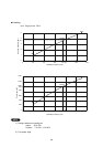
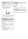
7-2. Recommended Wire Length and Diameter
Regulations on wiring diameter differ from locality to locality. For field wiring requirements, please refer to your
local electrical codes. Carefully observe these regulations when carrying out the installation.
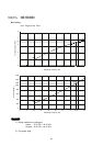
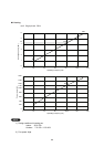
Table 2 lists recommended wire lengths and diameters for power supply systems.
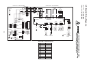
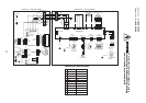
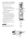
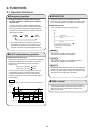
Refer to the wiring system diagram (Fig. 6) for the meaning of “A”, “B” and “C” in Table 2.
Table 2
NOTE
INDOOR UNIT
OUTDOOR UNIT
TERMINAL
TERMINAL
(B)
(A)
(C)
GROUNDING LINE
Power supply:
Single-phase 220 – 240VAC 50Hz
1
4
2
1
4
2
L
N
Fig. 6
CAUTION
Be sure to connect the power
supply line to the indoor unit
as shown in the wiring dia-
gram. The outdoor unit draws
its power from the indoor unit.
WIRING SYSTEM DIAGRAM
WARNING
●
Be sure to comply with local
codes on running the wire
from the indoor unit to the
outdoor unit (size of wire
and wiring method, etc.).
●
Each wire must be firmly
connected.
●
No wire should be allowed
to touch refrigerant tubing,
the compressor, or any
moving part.
●
To avoid the risk of electrical shock, each air
conditioner unit must be grounded.
●
For the installation of a grounding device,
please observe local electrical codes.
●
Grounding is necessary, especially for units
using inverter circuits, in order to release
charged electricity and electrical noise caused
by high tension. Otherwise, electrical shock
may occur.
●
Place a dedicated ground more than 2 meters
away from other grounds and do not have it
shared with other electric appliances.
WARNING
Cross-Sectional (A)+(B) (A) Power Supply Wiring Length (m) (C) Control
Fuse or Circuit
Area (mm
2
) (B) Power Line Length (m) Line Length (m)
Model 2 3.5 0.75
Breaker Capacity
CRV93 60 100 160
10A
CRV123 60 100 160