


A
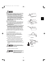
3-13-3. Wiring the ceiling panel
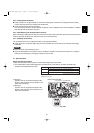
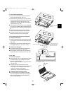
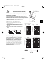
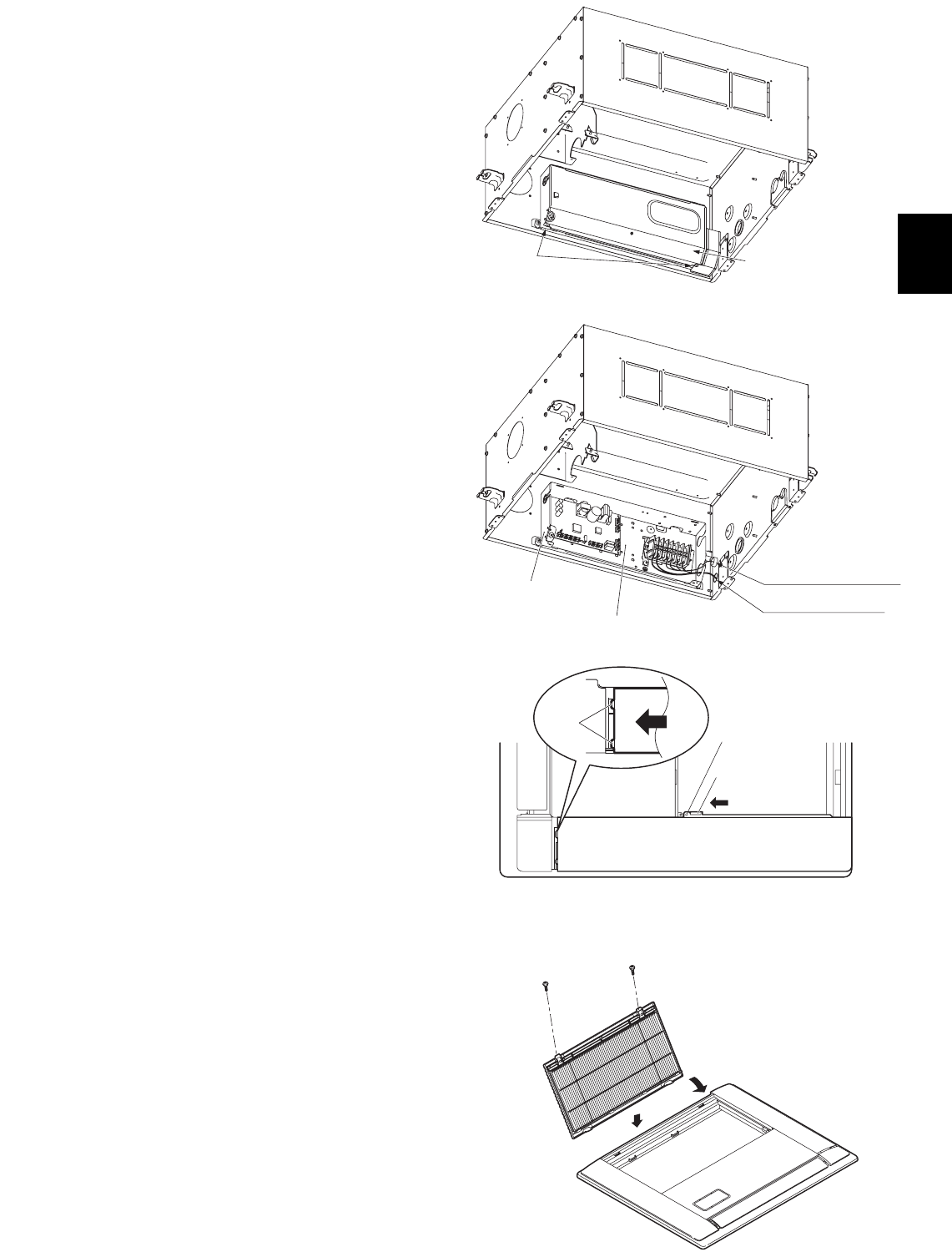
(1) Loosen the 2 screws on the electrical component
box lid, and remove the lid. (Fig. 3-57)
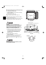
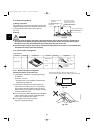
(2) Fasten the wiring connector (7P, red) which comes
out from the ceiling panel using the lead wire clamps
(2 locations) on the unit. Then connect it to the
connector (7P, red) inside the indoor unit electrical
component box. (Fig. 3-58)
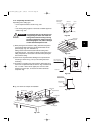
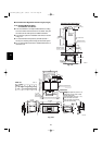
● If the connector is not connected, “P09” is displayed
on the remote controller, and the automatic flap will
not operate. Be sure to securely connect the connec-
tor.
● Check that the wiring connector is not pinched
between the electrical component box and the lid.
● Check that the wiring connector is not pinched
between the indoor unit and the ceiling panel.
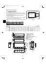
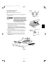
3-13-4. Installing the side panel and intake grille
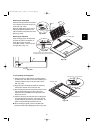
A. Installing the side panel
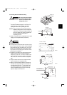
(1) Grasp the side panel finger grip and slide the panel
in the direction of the arrow to install the side panel.
(Fig. 3-59)
(2) Fasten the side panel onto the ceiling panel using
the supplied screws (4 × 12 or 5/32" × 15/32").
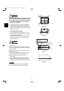
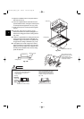
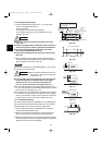
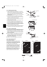
B. Installing the intake grille
● To install the intake grille, follow the procedure for
removing it in the reverse order. (Fig. 3-60)
● When installing the intake grille, be careful that the
flap lead wire does not become pinched. (Fig. 3-60)
3-13-5. Other
A. Check after installation
● Check again that there is no gap between the indoor
unit and the ceiling panel, or between the ceiling
panel and the ceiling surface.
* If there is a gap, then water leakage and condensa-
tion may occur.
● Check that the wiring connections are secure.
* If the wiring is not connected, the automatic flap will
not operate. (“P09” is displayed on the remote
controller.) In addition, water leakage,
condensation, and other problems may occur.
B. If a wireless remote controller is used
● For details concerning the installation procedure,
refer to the installation manual which was supplied
with the optional wireless remote controller and
indoor unit internal receiver.
Screw
Electrical compornent
box cover
Electrical compornent box
Indoor unit connector
Power supply outlet
Inter-unit control wiring
Fasten with screws
Tab
Tabs
Slide
Slide the side panel so that the side panel tabs are fastened to
the ceiling panel. Then fasten in place with the supplied screws
(4 × 12 or 5/32" × 15/32").
(4 × 12 or 5/32" × 15/32")
Screw
Screw
Fig. 3-57
Fig. 3-58
Fig. 3-59
Fig. 3-60
39
07-056 Mini_ECOi_II_NA 3/19/07 2:40 PM Page 39