


32
A
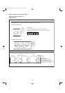
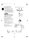
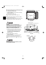
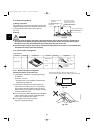
■ 1-Way Air Discharge Semi-Concealed Type (A Type)
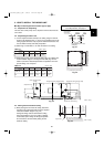
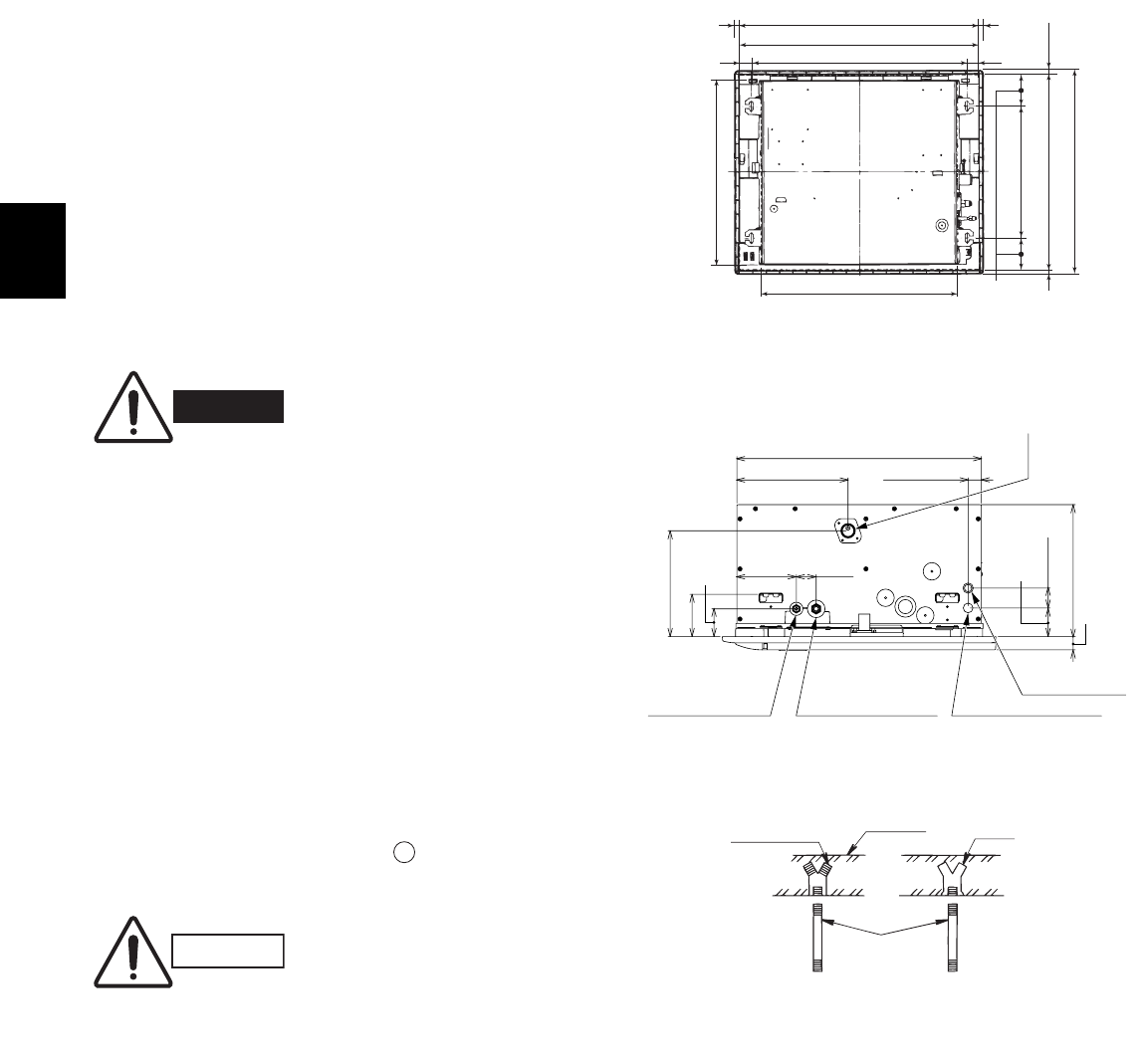
3-8. Suspending the Indoor Unit
(1) Follow the diagrams to make the holes in the ceiling.
(Figs. 3-29 and 3-30)
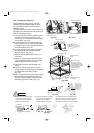
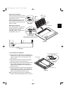
(2) Depending on the ceiling type:
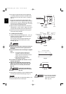
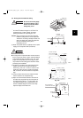
● Insert suspension bolts as shown in Fig. 3-31
or
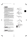
● Use existing ceiling supports or construct a suitable
support as shown in Fig. 3-32.
● Make sure that the length of suspension bolts from the
bottom of the unit is 19/32 in. or more. (Fig. 3-33)
Fig. 3-29
Hole-in-anchor
Hole-in-plug
Concrete
Insert
Suspension bolt
(M10 or 3/8")
WARNING
It is important that you use extreme care in
supporting the indoor unit from the ceiling. Ensure
that the ceiling is strong enough to support the
weight of the unit. Before hanging the unit, test the
strength of each attached suspension bolt.
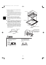
(3) Calculate the suspension bolt pitch using the full-
size installation diagram (printed on the package).
The relationship between the positions of the
suspension lugs, unit, and ceiling panel is as
shown in Fig. 3-30.
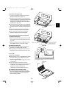
(4) Cut the ceiling material, if necessary.
(Figs. 3-29 and 3-30)
If the system requires fresh air to be drawn into the unit,
cut and remove the insulation (both externally and
internally) at the location shown as in Figs. 3-34 and
3-35.
A
When making the cuts to the insulation, be careful
not to damage the drain pan.
CAUTION
Fig. 3-31
Fig. 3-30
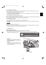
3-47/64
19/32
19/32
28-47/64 (Ceiling opening dimension)
23-15/64 (Ceiling opening dimension)
29-59/64 (Panel outer dimensions)
24-13/32 (Outline dimension of panel)
25-63/64 (Suspension bolt pitch)
1-27/64
(1-27/64)
23-5/8
22-3/64
15-3/4 (Suspension bolt pitch)
Unit: in.
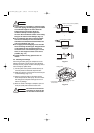
Flared refrigerant
connection outlet
(liquid tube)
Flared refrigerant
connection outlet
(gas tube)
Inter-unit
Control Wiring
Power supply outlet
Drain pipe connection
(Be sure to connect the supplied flexible hose.)
22-3/64
10-1/32
5-19/64 1-49/64
9-29/64
3-3/16
2-31/64
2-9/16
1-49/64
1-3/16
12-19/64
1-19/64
Unit: in.
07-056 Mini_ECOi_II_NA 3/19/07 2:40 PM Page 32