


12_ Initialization
initialization
BASIC OPERATIONS
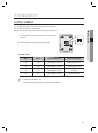
Initial State (when the power is supplied)
When you apply power to the product, it will sound beep three times before entering Standby with the red indicator
turned on.
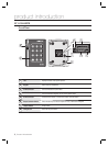
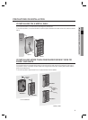
Using the card
Present the card to the product until you hear a beep and the green indicator turns on.
The reader keeps the green indicator turned on while transferring the card data to the
controller.
When it is done, the green indicator turns off and for receiving the next card, the red
indicator stays ON.
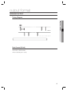
Using the keypad
Hold down the keypad until you hear a beep. The reader transfers the keypad data to the controller.
If the output format of the keypad is the option to 26bit Wiegand, pressing any key of the keypad turns on orange
indicator, and green indicator blinks when [ENT] is pressed after the input. The red indicator stays on after
transferring data to the controller. By default, it is 8-bit burst. Hence, keypad input and pressing [ENT] will blink the
green indicator only when you change the option to 26bit Wiegand.
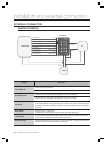
LED Control
You can control the red, green and orange indicators as necessary.
To control the red indicator, connect the relay output NO port of the controller to the red indicator control input line
(white line with red stripes), and connect the GND line to the COM line. Set I/O of the controller; now you can
control turning on/off the indicators.
You can turn on/off the indicators according to the I/O settings of the controller, which can be applied to various
situations.
For more information about the I/O settings of the controller, refer to the user manual of the controller.
Connect the yellow line for the green indicator, or the blue with white stripes for the orange indicator, to the COM
port of the controller.
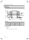
Buzzer Control
Connect the buzzer control input line (blue) to the NO port of the controller relay output, and GND to the COM port.
You can confi gure the I/O settings of the controller so that it beeps. If the product continues to beep, it means that
the buzzer control is working properly.
The controller can use the I/O settings to set the buzzer control so that it sounds an additional beep for authorized
or unauthorized access upon user authentication.
Furthermore, you can make various modifi cations according to the different I/O settings of the controller.
For more information about the I/O settings of the controller, refer to the user manual of the controller.
Card reading is not available while the buzzer control is sounding the buzzer.
Tamper Control
You can set the signal that you want to output if the device is dismantled forcibly.
Connect the COM port (gray line) of the product’s tamper switch to GND; connect the NC port (green with white
stripe) of the tamper switch to the input port of the controller. If the tamper of the reader operates, the controller
produces an input signal and generates the corresponding output depending on the controller setting.
X Y Z
[ \ ]
^ _ `
lzj lu{
W
zzhTzYWWW
X
Y
Z
[
\
]
^
_
`
lz
j
l
z
j
W
i
z
z
h
Tz
Y
W
W
W