


10_
Installation and External Connection
installation and external connection
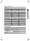
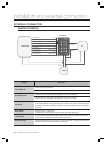
EXTERNAL CONNECTION
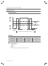
WIRING DIAGRAM
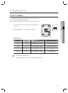
Category
Cable Color
Power Supply Unit
Connect the DC+12V to the red line.
Connect GND to the black line.
Wiegand Connection
Connect the green line of the product to the Wiegand D0 input port of the controller.
Connect the white line of the product to the Wiegand D1 input port of the controller.
LED Control
Enables you to turn on or off the LED indicators.
To control green indicator, connect the yellow line to the controller’s output (relay). Connect the blue with
white stripes to control the orange indicator, connect the white with red stripes to control the red indicator.
(see page 12)
Buzzer Control
Enables you to turn on or off the buzzer.
To control the buzzer, connect the blue line to the controller’s output (relay).
(see page 12)
Tamper Control
Connect the COM port (gray line) of the product’s tamper switch to GND; connect the NC port (green line
with white stripe) of the tamper switch to the input port of the controller.
RS-232 Connection
Connect to the COM port of the PC. (Connect pin 2 of the DB-9 connector to the purple line; connect the
black of the device (RS-232 GND) to pin 5 of the DB-9 connector)
X Y Z
[ \ ]
^ _ `
lzj lu{
W
zzhTyYWWX
Wiegand Data 0 Out
Wiegand Data 1 Out
PC
POWER
CONTROLLER
SSA-R2001
Red Black
DC +12V GND
RS-232(GND)
RS-232(TX)
Purple
Black
Tamper Switch Out(NC)
Tamper Switch Out(COM)
Buzzer Control In
LED Control In(Red)
LED Control In(Green)
LED Control In(Orange)
Green
White
Green with white stripes
Gray
Blue
White with red stripes
Yellow
Blue with white stripes