


SECTION 7: GAS SERVICE INSTALLATION
33
SECTION 7: GAS SERVICE INSTALLATION
7.1 Install Gas Supply Lines
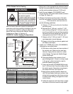
A 3/8" gas supply connection is required as shown in
Figure 32. To check system pressure, a plugged 1/8"
NPT tapping is required upstream of the manual gas
shut-off valve supplied with the heater.
Before connecting the heater to the supply system,
(Figure 32) verify that all high pressure testing of the
gas piping has been completed. Do not high pres-
sure test (greater than 1/2" psi/3.5 kPa) the gas
piping with the burner connected. The appliance
must be isolated from the gas piping system by clos-
ing manual gas shut-off valve during any pressure
testing at pressures less than or equal to 1/2" psi (3.5
kPa).
Follow these instructions to ensure a safe gas supply
system installation:
1. Support all gas piping with suitable pipe hanging
materials.
2. Use wrought iron or wrought steel pipe and mal-
leable iron fittings. The use of copper tube and
brass fittings is acceptable when such use is in
compliance with local codes. All pipe, tube and fit-
tings should be new and free from defects. Care-
fully ream the pipe and tube ends to remove
obstructions and burrs.
3. Use LP gas resistant joint compound on all
threads.
4. Check the pipe and tube connections for leaks
before placing heating equipment into service.
When checking for gas leaks, use a soap and
water solution; never use an open flame.
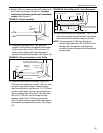
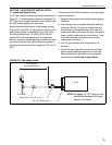
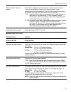
FIGURE 32: Gas Supply Lines
Heater
Pipe Union
Manual Gas Shut-off Valve
3/8" NPT Pipe Nipple
Not Supplied
by Roberts-Gordon
NOTE: A plugged 1/8" NPT tapping must
be provided upstream of the gas
supply to the heater.