


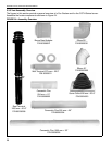
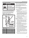
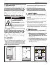

SECTION 5: VENTING INSTALLATION
25
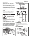
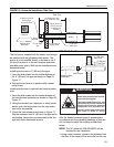
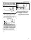
9. Attach 3" (80 mm) elbow portion of 90° elbow kit to
the 3" (80 mm) flue pipe (length 'A'). Use high
temperature silicone sealant and 3 sheetmetal
screws. (See Figure 21)
FIGURE 21: Elbow Assembly
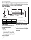
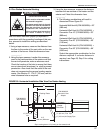
10. Completely assemble the 3” (80 mm) vent
lengths A, B and elbow and attach to the heater.
Put the vent collar on the 3” (80 mm) vent. All
joints must be sealed with high temperature
sealant and sheet metal screws. (See Figure 22)
FIGURE 22: Elbow Assembly for Vent Collar
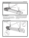
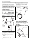
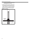
11. Attach the vent collar to the heater. Hold the 5”
(125 mm) vent material up to the 3" (80 mm) vent
and mark the required length. Note the length
must be sufficient for a minimum of 1 1/2” (38 mm)
overlap at both ends. Cut the vent to length from
the non crimped end. Wrap the 3” (80 mm) tube
with the 5” (125 mm) vent and snap the vent
together. Attach the 5” (125 mm) vent at both
ends. All joints must be sealed with high tempera-
ture sealant and sheet metal screws. (See Figure
23)
FIGURE 23: Vent Collar and 5" Vent Attachment
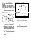
12. Insert vent terminal and repeat step 11 for 5” (125
mm) from the elbow through the wall. Secure the
vent terminal to the exterior surface of the wall.
NOTE: If the protruding 3" (80 mm) flue pipe is
directly below and within 24" (610 mm) of the
building soffit, the optional vent extension
should be used and secured with three sheet-
metal screws.
High
Temperature
Silicone
3x Self
Drill Screws
Spring
5 (125 mm)
Elbow
Heater
5 (125 mm) Vent Collar
Stainless
Steel Tab
on
Turbulator
3x Self Drill Screws and
High Temperature Silicone
Spring
3 (80 mm)
5 (125 mm)
3x Sheetmetal Screws and
High Temperature Sealant
1 1/2 Min. (38 mm)
1 1/2 Min.
(38 mm)
1 1/2 Min. (38 mm)
1 1/2 Min. (38 mm)