


CGTH INSTALLATION, OPERATION AND SERVICE MANUAL
20
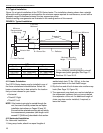
4.14 Grille Installation (for Select Models Only)
A protective grille is included with select models of the
CGTH-Series heater. This grille is supplied in sections
and must be installed on the underside of the reflector
prior to operation.
Grille sections are held in position by a channel formed
by the rolled edge of the reflector. The shorter length
8' (2438 mm) heater requires installation of two
protective grille sections, while the longer heater (11' 6")
(3505 mm) requires three protective grille sections.
Grille Section (P/N 08050001) is open-ended and
installed along the length of the reflector. Grille End Cap
(P/N 08050002) is the formed end cap and is installed
at the end of the grille that is furthest from the burner.
Installation:
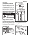
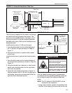
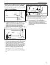
Step 1. Silicone Cap Installation (See Figure 12).
• Silicone caps (P/N 91915951) are to be placed
along each side of the grille at both end fingers and
the center finger.
FIGURE 12: Silicone Cap Installation
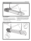
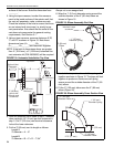
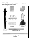
Step 2. Attach grille end cap to final grille section
(See Figure 13).
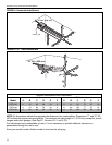
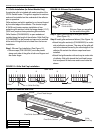
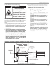
Step 3. Install grille sections as follows: (See Figure 14)
• Attach first grille section(s) (P/N 08050001) to under-
side of reflector as shown. The wires of the grille will
rest in the channel formed by the rolled edges of the
reflector. Be certain the silicone caps have been
installed.
• Attach final grille section with end cap to under side
of reflector. Butt grille toward the front fixed hanger
that is adjacent to the burner and to each other as
shown.
FIGURE 13: Grille End Cap Installation
FIGURE 14: Reflector and Grille
Silicone Cap
P/N 91915951
Grille
Finger
Silicone Caps are supplied
for the ends of the grille.
Bend up 90°
3
Pull outward
4
SIDE VIEW
2
Grille
Grille End Cap
1
Grille
End Cap
Burner
Front Fixed Hanger
Reflector
First Grille Sections
Final Grille Section
Description Part Number
Grille Section 08050001
Grille End Cap 08050002