


SECTION 5: VENTING INSTALLATION
29
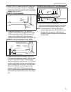
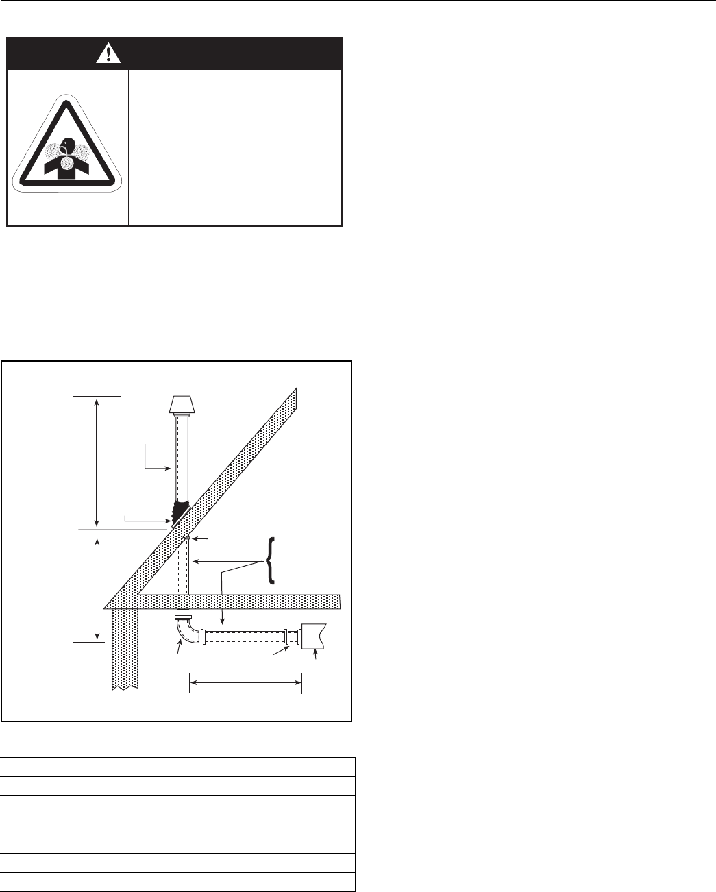
5.5 Cox Geelen Vertical Venting
After the heater has been properly suspended in
accordance with the preceding headings of this sec-
tion, proceed to install the venting as described
below. Be sure to observe the General Venting
Guidelines on Page 14, Section 4.5.
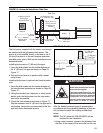
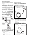
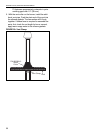
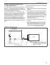
FIGURE 28: Vertical Venting Configurations
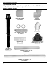
Table 2: Components
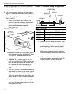
1. Using a saw, cut an appropriate size clearance hole in
the roof to accommodate the vertical run of vent pipe
and the vent termination (minimum 5" [125 mm]).
2. Install the vent adapter (P/N 90506012) and
secure with #8 x 3/8" sheet metal screws as shown
on Page 28, Figure 26.
3. Measure the distance to the center of the hole
from the vent adapter. Note this dimension here
_________. If the concentric vent has to be cut,
use the following guidelines:
A. Subtract 1.5" (38 mm) to allow for the elbow
and both joints.
B. Separate the 3" (80 mm) and the 5" (125
mm) vent by pulling the 3" (80 mm) vent out
from the end with the internal silicone gasket.
Remove the internal spring from the non-sili-
cone gasket end of the 5" (125 mm) vent.
C. Always cut the 3" (80 mm) and 5" (125 mm)
vent separately to avoid damage.
D. Always cut from the non-silicone gasket end
and deburr thoroughly.
4. Install a 4-7" EPDM storm collar (P/N 90506015)
following the instruction below:
A. Slide storm collar down over lower section of
the vertical vent. Water can be used as a
lubricant. Apply silicone sealant on under-
side of flange. Turning back flexible flange
makes this simple.
B. Press pipe flashing into contours of roof
panel configuration. If there is a sharp angle
in the panel, a blunt tool can be used to
press the flashing into place.
C. Lower roof terminal (P/N 90506008) through
the 5" (125 mm) hole. From the inside ensure
the vent is square. Secure the vent clamp to
the inside of the roof. See Figure 28.
D. Apply silicone sealant between base and
roof. Drill and fasten flashing to surface. Use
a blunt tool to press base into sharp corners
of valleys while drilling; and against to insert
rivet or screw.
E. Follow the sequence: drill two holes on oppo-
site sides of aluminum base through sheet.
Part Number Description
90506001 Elbow 90°
90506003 Concentric Flue 10" (254 mm)
90506004 Concentric Flue 20" (500 mm)
90506005 Concentric Flue 39" (1000 mm)
90506008 Roof Terminal 50.5" (1283 mm)
90506012 Burner/Vent Adapter
Carbon Monoxide Hazard
Heater must be exhausted outside.
Use materials supplied.
This heater needs fresh air for safe
operation and must be installed so
there are provisions for adequate
combustion and ventilation air.
Failure to follow these instructions
can result in death or injury.
WARNING
B
VERTICAL
30 (762 mm)
minimum
above roof
Vent
Clamp
Storm
Collar
90506003
90506004
90506005
90506012
Burner
A
Use Table 2 to select lengths for A & B
Roof
90506001
Roof
Terminal
90506008