


SECTION 5: VENTING INSTALLATION
21
SECTION 5: VENTING INSTALLATION
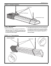
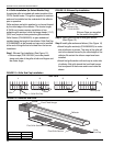
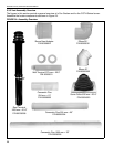
Vent configuration 1 is for the galvanized vent mate-
rial, See Pages 22 through 25. Vent configuration 2 is
for the Cox Geelen vent material, See Pages 26
through 30. The galvanized vent material is available
for horizontal installation only. The Cox Geelen vent
style can be installed horizontally or vertically. The
maximum overall vent length is 10’ (3 m) with only
one 90° elbow. The flue must be self supporting.
5.1 General Venting Requirements
This heater must be vented in accordance with the
following national codes and any local codes which
may apply:
United States: Refer to ANSI Z223.1 - latest revision.
Canada: Refer to CAN/CGA-B149.1 and B149.2 -
latest revision.
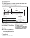
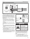
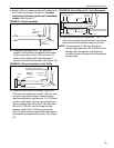
Vent terminal must be installed at a height sufficient
to prevent blockage by snow and protect building
materials from degradation by flue gasses.
Vent must exit a building not less than 7' (2.1 m)
above grade when located adjacent to public
walkways.
For galvanized venting, seal all joints with high tem-
perature silicone sealant.
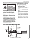
United States Requirements
Vent must terminate at least 3' (.9 m) above any
forced air inlet located within 10' (3 m).
Vent must terminate at least 4' (1.3 m) below, 4'
(1.3 m) horizontally from, or 1' (.3 m) above any door,
window, or gravity inlet into any building.
Vent terminal shall be located at least 1' (.9 m) from
any opening through which vent gasses could enter a
building.
Canadian Requirements
Vent terminal must not be installed less than 3' (.9 m)
from any building opening.
Vent terminal must be installed at least 3' (.9 m)
above grade.
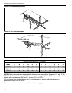
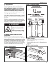
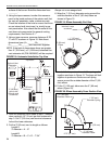
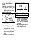
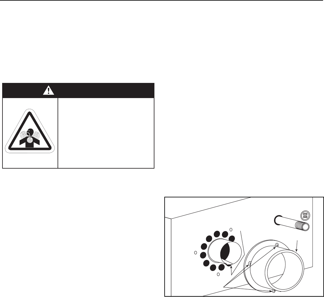
5.2 Install Galvanized Collar
For all galvanized flue installations, the galvanized
collar (See Figure 15) is shipped loose in the carton.
For ease of installation, the vent collar should be
installed on the rear surface of the burner before the
heater is suspended. Install the galvanized collar as
follows:
1. Apply a bead of high temperature silicone sealant
to the mating surface of the galvanized collar
mounting flange.
2. Align the three mounting holes of the galvanized
collar with the three galvanized collar mounting
holes on the rear surface of the burner.
3. Using a #2 phillips head screwdriver, or 1/4" nut
driver, secure the galvanized collar to the rear sur-
face of the burner with the three screws (#8 x 3/8"
10 mm long) provided in the accessories bag sup-
plied with the heater.
FIGURE 15: Rear View
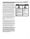
Carbon Monoxide Hazard
Heater must be exhausted outside.
Use materials supplied.
This heater needs fresh air for safe
operation and must be installed so
there are provisions for adequate
combustion and ventilation air.
Failure to follow these instructions
can result in death or injury.
WARNING
Vent Collar
Turbulator end tab bent
over the heat exchanger
3x #8 3/8
Mounting Screws