CGTH INSTALLATION, OPERATION AND SERVICE MANUAL
18
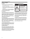
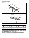
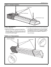
4.10 Typical Installation
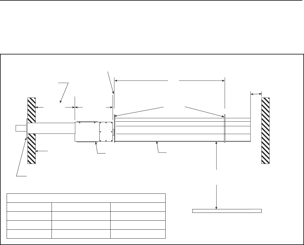
Figure 9 is a typical installation of the CGTH-Series heater. The installation drawing shown has a straight
horizontal venting arrangement and specifies the minimum space required for maintenance, as well as the
allowable range of distances between the two suspension points.
Detailed venting arrangements are illustrated in the venting section of this manual.
FIGURE 9: Typical Installation
1" (25 mm)
Maximum
6" (152 mm) Minimum
Vent Terminal
Exterior Wall
Burner Box
Reflector
Suspension
Points
Minimum
Recommended
for Servicing
Minimum Mounting
Height - 7' (2133 mm)*
24"
(610 mm)
15"
(381 mm)
X
X Dimension
Model Minimum Maximum
CGTH-30 60" (1524 mm) 72" (1829 mm)
CGTH-40 102" (2590 mm) 114" (2895 mm)
CGTH-50 102" (2590 mm) 114" (2895 mm)
(*) For minimum mounting height in aircraft
hangars and public garages,
See Page 11,
Sections 3.5.1 and 3.5.2.
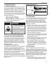
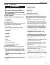
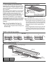
4.11 Heater Orientation
The CGTH-Series heater may be installed in any of
the three orientations indicated below. Select the
heater orientation that is best suited for the location
that you have chosen for your heater.
• Horizontal
• Tilted 45° Right
• Tilted 45° Left
NOTE: If the heater is going to be vented through the
roof, be sure to carefully review the roof option
installation instructions on Pages 29 and 30.
Ensure that the selected mounting site will satisfy
the measurement parameters (vent length not to
exceed 10' [3048 mm]) described in that section.
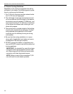
4.12 Horizontal Installation
For Horizontal Installation:
1. Using snap hooks, attach two equal lengths of
welded steel chain 75 lbs. (33 kg), to the two
uppermost holes in the front fixed hanger.
2. Slip the free end of both chains onto another snap
hook (See Page 19, Figure 10).
3. The uppermost snap hook can now be installed on
the suspension hardware that you have installed
for suspension of the unit. An additional length of
chain may also now be installed, if required, to
lower the heater.


