


14
• RUN GAS SUPPLY
For pipe sizing, refer to your local gas
installation codes.
• PURGE SUPPLY OF AIR AND
DEBRIS
All foreign materials such as filings must
be purged from the gas supply, as they may
cause the gas valve to malfunction.
A means to measure the gas pressure
immediately upstream of the supply
connection to the appliance shall be
provided by the installer.
Connect and tighten union.
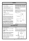
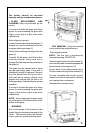
Use only an approved B vent system
• Position the heater.
• Suspend a plumbline from the ceiling to
the centre of the flue socket.
• Mark the centre of the flue in the ceiling.
• Make a small hole in the ceiling and
double check that the flue system will be
at least 1” clear of combustible
materials.
• Cut the hole for the flue.
• Fit the ceiling plate, flue and decorative
cover.
The decorative cover must be able to slide
up to give access to the flue collar. The
inner flue must be supported independently
of the heater but allowing sufficient
movement to allow connections to and
disconnections from the flue collar.
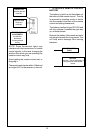
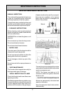
It is recommended that the flue be
installed vertically only. If installation
prevents this then there must be at
least 4 feet of vertical flue before any
bends. The flue must not fall below
VENTING
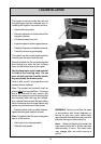
GAS CONNECTION
On completion of work, check for gas
leaks.
Use a soapy solution all gas connections.
Leaks will be visible when the soapy
solution forms bubbles. When finished wipe
soapy solution with rag to remove residue.
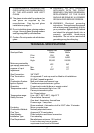
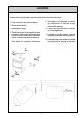
Gas inlet
3/8” FNPT
10
5
/8”
10.6”
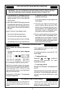
horizontal at any stage. There must not
be more than 2 bends in any system.
Any horizontal section of flue must be
less than 1/3 the length of vertical flue
which follows it.
See below diagram
An approved B vent system must be
attached by mechanical means to the flue
spigot and sealed using an approved high
temperature sealant.
**
X/3 maximum
maximum
2 bends
10 ft
Minimum **
4 ft
minimum
X
** Refer to local codes for other minimum
requirements.