


4/38
FV-G030B1
User’s Guide Rev. 1.02
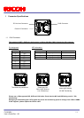
1.2 DC Iris Lens Connector
M1951 (EMUDEN) or equivalent.
Pin Assignment
Pin No. Signal Name
1 DAMP-
2 DAMP+
3 DRIVE+
4 DRIVE-
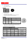
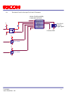
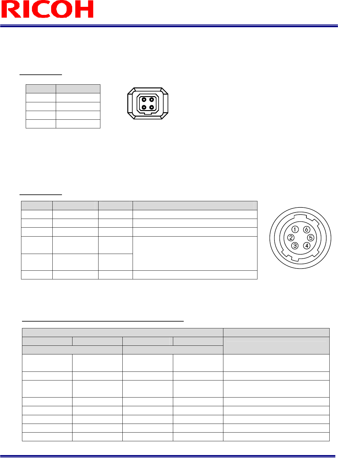
1.3 Power-I/O Connector
HR10A-7R-6PB(Hirose)or equivalent
This connector is for the power supply (12Vdc) and input /output signals.
Use HR10A-7P-6S (Hirose) or equivalent for the cable side.
Pin Assignment
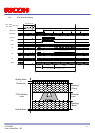
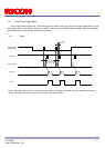
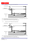
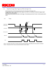
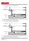
Output signals can be assigned through the camera setting communication.
(Device Code = 00H, Command = F0H and F1H)
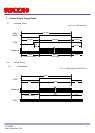
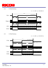
IO Signal Patterns for Pin No.2 (I/O-1) and Pin No.3 (I/O-2)
Pin No.
Signal Name
IN / OUT
Voltage
1 GND IN 0V
2 I/O-1 OUT +3.3V LVTTL
3 I/O-2 OUT
+3.3V LVTTL
4 TRG_In- IN
5 TRG_In+ IN
Low: Smaller than +1.0V (Opt. Isolated -)
High: +3.0 to +26.4V (Opt. Isolated +)
*potential difference between TRG_In- and
TRG_In+
6 POWER IN IN +10.8 to +26.4 Vdc
Command No. HR10A-7R-6PB (Hirose)
F0H[3..0] F1[3] F0H[7..4] F1[4]
For I/O-1 (Pin No. 2) For I/O-2 (Pin No.3)
I/O-1 (Pin No.2) / I/O-2 (Pin No.3)
0H
(initial setting)
- 0H -
FrameTriggerWait
(initial setting for I/O-1)
1H Set Value 1H Set Value UserOutput
2H -
2H
(initial setting)
ExposureActive
(initial setting for I/O-2)
3H - 3H - TriggerAuxiliary
4H - 4H TriggerInternal
5H - 5H SensorReadOut
6H - 6H StrobeSignal
7H-FH - 7H-FH - For Test Use Only
1 2
3 4