


30/38
FV-G030B1
User’s Guide Rev. 1.02
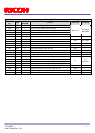
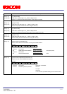
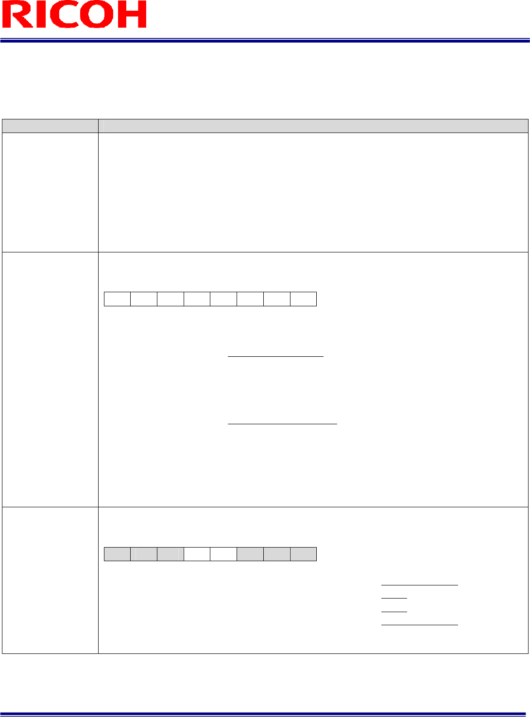
Command No. Command Description
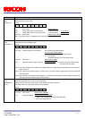
90H:
STROBEON_I[7..0]
91H:
STROBEON_I[15..8]
92H:
STROBEON_I[23..16]
93H:
STROBEON_F[7..0]
[Active time (us) for the strobe signal]
Initial data: STROBEON _I[23..0] =10, STROBEDELAY _F[7..0] = 0, data range: 0 to 2,000,000
Active time for the strobe signal = (STROBEON _I[23..0]). (STROBEON _F[7..0]) useconds
Active time for the strobe signal is set as below.
0: No strobe signal output
1 to 9: 10 us
Greater than 9: set value
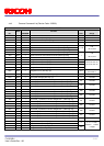
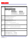
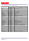
F0H:
OUTSEL
[7..0]
[Output signal selection for the power-I/O connector] Initial data: OUTSEL[7..0] = 20H
Sets the output signal from the power/IO connector.
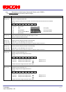
D[7..0]
D7 D6 D5 D4 D3 D2 D1 D0
D7 to D4: Output signal for 3pin of the power/IO connector
0: FrameTriggerWait signal
1: UserOutput signal
2: ExposureActive signal 3: TriggerAuxiliary signal
4: TriggerInternal signal (after mask and delay process)
5: SensorReadOut signal
6 to F: No Function (Prohibited setting. Do not set these values)
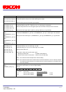
D3 to D0: Output signal for 2pin of the power/IO connector
0: FrameTriggerWait signal
1: UserOutput signal
2: ExposureActive signal 3: TriggerAuxiliary signal
4: TriggerInternal signal (after mask and delay process)
5: SensorReadOut signal
6 to F: No Function (Prohibited setting. Do not set these values)
Note: When “UserOutput signal” is selected, set the status of the signal with “UserOutput signal for the
power/IO connector (TEST2-D3,4)”.
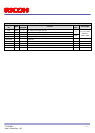
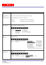
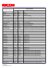
F1H: TEST2[7..0]
[UserOutput signal for the power-I/O connector] Initial data: TEST2[7..0] = 00H
Sets the status of the UserOutput signal.
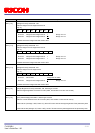
D[7..0]
D7 D6 D5 D4 D3 D2 D1 D0
D7 to D5:
No function Always set as “000”
D4: UserOutput signal for 3pin of the power/IO connector 0: Low 1: High
D3: UswerOuput signal for 2pin of the power/IO connector 0: Low 1: High
D2 to D0:
No function Always set as “000”
Note: The UserOutput signal is enabled whenever “UserOutput signal” is selected at the “Output signal
selection (OUTSEL)”.