


CONNECTIONS – PLUMBING
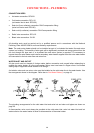
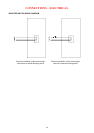
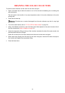
This water heater has either a plastic dip tube or fitting
liner in the inlet and outlet fittings (see diagram). These
must be in place for the water heater to function properly.
Do not remove or damage them by using heat nearby.
They will be pushed into the correct position as the fitting
is screwed in.
PIPE SIZES
To achieve true mains pressure operation, the cold water line to the water heater should be the same
size or bigger than the hot water line from the water heater.
The pipe sizing for hot water supply systems should be carried out by persons competent to do so,
choosing the most suitable pipe size for each individual application. Reference to the technical
specifications of the water heater and local regulatory authority requirements must be made.
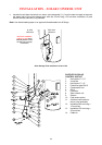
IN-SERIES WATER HEATER (IF INSTALLED)
The pipe work between the solar storage tank and an in-series water heater has a minimum
recommended pipe size of DN20,
MUST BE of copper and be fully insulated in accordance with the
requirements of AS/NZS 3500.4. The insulation must be weatherproof and UV resistant if exposed. The
insulation must be fitted up to the connections on both the solar storage tank and the in-series water
heater. An isolation valve must be installed on the water line to the in-series water heater.
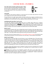
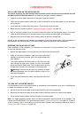
RELIEF VALVE
The temperature pressure relief valve is shipped either under the top flap of the water heater carton or
behind the front cover. The temperature pressure relief valve must be fitted before the water heater is
operated. Before fitting the relief valve, make sure the probe has not been bent. Seal the thread with
Teflon tape - never hemp. Make sure the tape does not hang over the end of the thread.
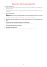
Screw the valve into the correct opening
(refer to the installation diagram on page 23) leaving the valve
outlet pointing downwards. Do not use a wrench on the valve body - use the spanner flats provided.
RELIEF VALVE DRAIN
A copper drain line must be fitted to the relief valve to carry the discharge clear of the water heater.
Connect the drain line to the relief valve using a disconnection union. The pipe work from the relief
valve to the drain should be as short as possible and fall all the way from the water heater with no
restrictions. It should have no more than three right angle bends in it. Use DN15 pipe. The outlet of the
drain line must be in such a position that flow out of the pipe can be easily seen (refer to
AS/NZS 3500.4) - but arranged so hot water discharge will not cause injury, damage or nuisance. The
drain line must discharge at an outlet or air break not more than 9 metres from the relief valve.
In locations where water pipes are prone to freezing, the drain line must be insulated and not exceed
300 mm in length. In this instance, the drain line is to discharge into a tundish through an air gap of
between 75 mm and 150 mm.
Warning: As the function of the temperature pressure relief valve on this water heater is to
discharge high temperature water under certain conditions, it is strongly recommended the pipe work
downstream of the relief valve be capable of carrying water exceeding 93°C. Failure to observe this
precaution may result in damage to pipe work and property.
29