


24
INSTALLATION – SOLAR CONTROL UNIT
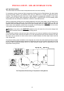
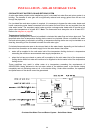
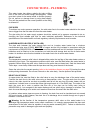
The solar control unit is designed to be mounted on the side of the solar storage tank, with its location
in between and offset from the cold water inlet and solar hot water inlet. The solar control unit, supplied
with a 1.8 metre power cord, requires a 240 V general power outlet (GPO) located within 1.2 metres of
its installation. The GPO must have a continuous power supply originating from a circuit other than the
water heater circuit. The GPO is required to be weatherproof if installed outdoors (refer to
“Connections
– Electrical”
on page 31).
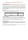
Note: Care must be taken when mounting the solar control unit to the side of the solar storage tank.
Damage to the cylinder as a result of mounting the solar control unit to the jacket will void the warranty
(refer to
“Saddling - Pipe Work” on page 21).
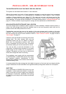
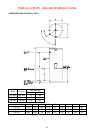
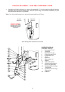
SOLAR STORAGE TANK WITH RAISED SOLAR HOT INLET
To connect the solar cold pipe and mount the solar control unit on a Streamline storage tank with a
raised solar hot inlet (and raised heating unit):
Numbers in parentheses
refer to items on diagram on page 25.
• Assemble a ½” x ½” hex nipple (1) into the branch outlet of the 4 way tee (2) (ensure the
compression end of the nipple is exposed) and the ½” x ¾” hex nipple (3) in the end of the 4 way
tee, so that when the assembly is fitted to the cold water inlet of the solar storage tank, the
compression nipple (1) is orientated vertically upwards and the cold sensor housing is orientated to
the rear of the solar storage tank. Fit the assembly to the cold water inlet of the solar storage tank.
• Connect the DN15 preformed pipe (4) to the branch tee connection, using the compression nut (5)
and olive (6) provided.
• Fit a ½” x ½” hex nipple (1) to the outlet of the circulator (7) mounted in the solar control unit (8)
(ensure the compression end of the nipple is exposed).
• Locate the solar control unit (8) by connecting the DN15 preformed pipe (4) to the nipple on the
inlet of the circulator (7) using the compression nut (5) and olive (6) provided.
• Secure the solar control unit (8) to the solar storage tank using the four screws (9) provided.
• Connect the solar cold pipe (to the collector) to the nipple (1) on the outlet side of the circulator (7)
using the compression nut (5) and olive (6) provided.
• Insert the cold sensor probe (10) into the cold sensor housing on the 4 way tee (2), ensuring the
‘O’ ring is in position on the probe. Lock it into position with the locking washer and clip provided.
• Connect the hot sensor lead (from the solar collector installation) to the hot sensor cable connector
at the underside of the solar control unit (8).
• Insulate the preformed pipe (4) with the 280 mm long x 12 mm diam insulation (12) and secure with
the cable ties (14) provided.
To connect the solar hot pipe to the solar storage tank:
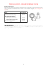
• Fit the air bleed valve and non return valve assembly (11) to the solar hot water inlet of the solar
storage tank. Ensure the bleed valve outlet is pointing downwards at 45° to the rear of the solar
storage tank, away from the solar control unit (8).
• Connect a copper drain line to the bleed valve (refer to
“Bleed Valve Drain” on page 30), using the
compression nut and olive provided.
• Fit a ½” x ½” hex nipple (1) to the end (inlet) of the air bleed valve and non return valve
assembly (11) (ensure the compression end of the nipple is exposed).
• Connect the solar hot pipe (from the collector) to the nipple (1) on the air bleed valve and non
return valve assembly (11) using the compression nut (5) and olive (6) provided.