


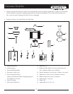
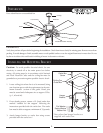
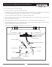
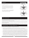

ELECTRICAL CONNECTIONS: Be sure electricity is turned off at the main power box before wiring
ELECTRICAL CONNECTIONS
7
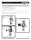
Wiring
box
Light
Switch
BLK
BLUE
WH
Fan controlled by
pull chain on fan.
Light controlled by
wall switch.
Ground to
mounting
bracket
BLUE
BLK
WH
WH
Fan
Light
Power lines
120V
G
R
O
U
N
D
BLK
WH
GREEN
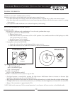
Fan controlled by
pull chain on fan.
Light controlled by
pull chain on light.
Ground to
mounting
bracket
Power lines
120V
BLUE
BLK
WH
WH
Fan
Light
G
R
O
U
N
D
BLUE
BLK
BLK
WH
WH
GREEN
Wiring
box
GRN
Wiring
Light
BLK
BLUE
WH
Fan and light controlled by
Ground to
BLUE
BLK
WH
Fan
Light
Power lines
GR
O
UN
D
BLK
WH
GREEN
Fan
independent approved speed/light wall controller
120V
box
switch
bracket
mounting
switch
WH
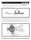
1. Four wires are connected to the fan.
Black – this is the “hot” power to run fan.
White – this is the “common” power to run fan and light.
Blue – this is the “hot” power for uplight and light kit.
Green – ground wire (on bracket or downrod).
2. If fan and light are to be connected to the same circuit, black and blue wires can both be connected to house circuit
black wire.
NOTE: The other end of the blue wire, (light circuit) is in the switch housing with a wire nut and label for light kit
attachment. The white wire (common for light kit) is also there.
*